Regulations: Rigging in the RAI
|
Documentname: |
Rigging in the RAI ENG – version 1.7 |
Article 1 - Introduction
Article 2 - Rigging guidelines
Article 3 - Entrance C: Canopy
Article 4 - Holland Terrace
Article 5 - Holland Lounge
Article 6 - Entrance F
Article 7 - Park Foyer
Article 8 - Entrance K
Article 9 - Hall 1
Article 10 - Hall 2
Article 11 - Hall 3
Article 12 - Hall 4
Article 13 - Hall 5
Article 14 - Hall 6
Article 15 - Hall 7
Article 16 - Hall 8
Article 17 - Hall 9
Article 18 - Hall 10
Article 19 - Hall 11
Article 20 - Hall 12
Article 21 - Hall 13
Article 22 - Auditorium Lounge and Onyx Lounge
Article 23 - Upper Lounge and Emerald Lounge
Article 24 - Diamond Lounge
Article 25 - Europe Foyer 1 and 2
Article 26 - Room G 102
Article 27 - Room E 103 – E 108
Article 28 - Room ceiling Auditorium
Article 29 - Stage tower Auditorium
Article 30 - Forum
Appendix I - Requirements for the rigging plan
Appendix II - RAI LIVE restrictions Hall 8, 9, 10 and 11
Appendix III - Example rigging plan
Appendix IV - Example calculations rigging plot
Article 1 - Introduction
This booklet shows where and under what conditions rigging is possible in RAI Amsterdam. For each part of the RAI we explain the locations for rigging and the maximum load per suspension point for both vertical rigging (straights) as well as multi-point bridles (bridles).
To set up a rig in our complex, the rigging party must first send a rigging plan to the RAI Account Manager of the relevant event or trade show four weeks before the beginning of the event or trade show. This document describes what the rigging plan must look like. Each rigging plan will then be evaluated against the criteria specified in this document. You will receive an official response from the RAI within five working days, after which possible adjustments can be made. An agreement on the definite version should be made two weeks before the start of the event or trade show.
Below is a floor plan of RAI Amsterdam (Figure 1). Each hall, entrance area and foyer has its own chapter, provided that rigging is possible.
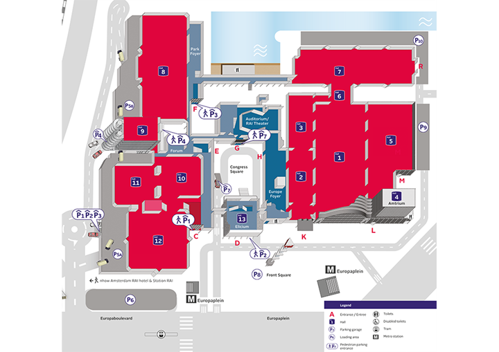
Figure 1: Floor plan of RAI Amsterdam
Article 2 - Rigging guidelines
The following applies when making any decisions: safety first! The following conditions must be met in order to set up rigging in the RAI:
Company and personnel certification
- Rigging may only be taken on by VCA*, VCA** or Oshas 18001 certified companies.
- Each rigger present must:
- carry a valid VCA certificate (VCA-B or VOL-VCA for operations managers).
- be able to prove that he holds an 'Elementaire Hijstechniek in de Entertainment Industrie' certificate or a variation of this such as a National Rigging Certificate (UK), Arena Rigging Certificate from ETCP (USA), Rigstar Rigging certificate (USA), or a relevant VLPT rigging diploma (GER).
- If a truck-mounted work platform is used, the operator must have the correct certificate. The rigger is responsible for ensuring that no third parties are present in his work zone.
- Anyone who uses a truck-mounted work platform must wear a full-body safety harness (EN361) attached to the platform by means of a lanyard (EN355).
- People (grounders) in the vicinity of the operating scope of the truck-mounted work platform must wear a helmet (EN397).
- Each rigging party involved must have a rigging plan approved by the RAI. A description of how the rigging plan must be submitted to the RAI is included in Appendix I. Your RAI Account Manager can also submit a sample rigging plan.
- Each part of the building described in this document has its own AutoCAD drawing on which the available suspension points are indicated.
- The maximum permissible load stated in this manual must not be exceeded.
- For multi-point bridles (bridles), the inside angle must be less than 120 degrees.
- The maximum permissible load for multi-point bridles is based on 2-point bridles. For multipoint bridles, the distribution of force at all points of application must be clearly calculated.
- Dynamic loads are not permitted without explicit consent from a designer chosen by the RAI, at the expense of the customer/contractor.
- Rigging must only be carried out in accordance with the plan: any changes must be discussed with the manager of the Technical Department at the RAI Amsterdam.
- For some parts of the building, the maximum permissible load is different in case of snow. The RAI is allowed to arrange for a load which has already been approved to be reduced to an acceptable weight
- The roof construction must not be damaged in any way.
- Fixed elements in the roof (such as lighting fixtures, blinds, blackout mechanisms, drains) must not be touched during rigging.
- Rigging may only be carried out using materials bearing CE marking.In the case of parties outside the EU, products must demonstrably fulfill the ASME or an equivalent directive.
- Materials must have a WLL inscription or label.
- The maximum permissible load is 0.5 times the (industrial) WLL
- Materials must be tested at least once a year and it must be possible for the test report to be produced within 24 hours on request.
- Materials must be used in accordance with instructions.
Requirements for the rigging plan
Rigging in practice
Use of materials
Note: At all times the RAI reserves the right to take down the rigging or to arrange for a load which has already been approved to be reduced (e.g. in case of snowfall) at any time. The rigging party should be aware that the RAI checks whether the suspension points have been constructed in accordance with guidelines and the rigging plan. If this is not the case, the RAI is authorised to reject the rigging. In the event of rejection, the RAI is not liable for any damages (such as financial damage or damage to image).
Article 3 - Entrance C: Luifel
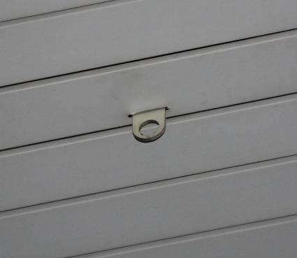
Figure 2: Suspension points Entrance C canopy
Height suspension point: height bottom edge = 9.50 m
In Entrance C, vertical rigging is allowed at the locations indicated. There are a total of 65 possible suspension points on the 2-dimensional framework.
Note: The canopy is fitted with a pigeon net which must not be damaged.
Note: Above wind force 6, all rigging must be taken down from the shed roof
 |
Vertical rigging (straight)
|
 " " |
Bridling (bridles)
|
 |
Snowfall
|
Article 4 - Holland Terrace
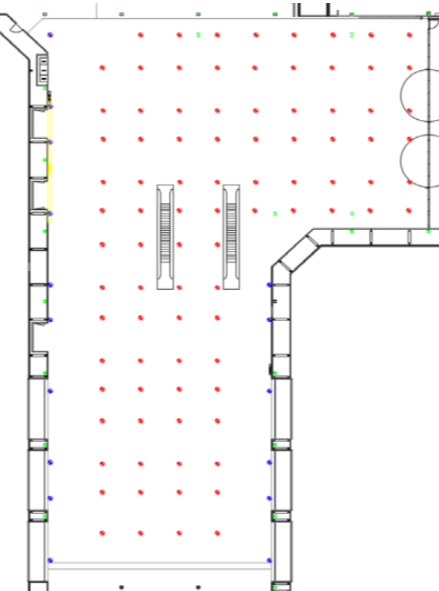
Figure 3: Holland Terrace suspension points
Height suspension points:
lower part = 9.50 m
higher part = 6.00 m
On the Holland Terrace, vertical rigging is allowed from the eyes in the ceiling. There are a total of 97 possible suspension points (see Figure 3).
|
Vertical rigging (straight)
|
|
|
Bridling (bridles)
|
|
Snowfall
|
Article 5 - Holland Lounge
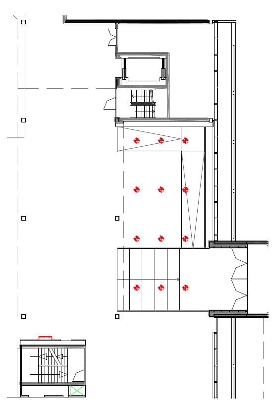
Figure 4: Suspension points in Holland Lounge
In the Holland Lounge, vertical rigging is allowed from eyes in the ceiling. There are a total of 9 possible suspension points (see Figure 4).
|
Vertical rigging (straight)
|
|
" |
Bridling (bridles)
|
|
Snowfall
|
Requirements for attachment to the roof construction:
 |
 |
Note: |
Article 6 - Entrance F
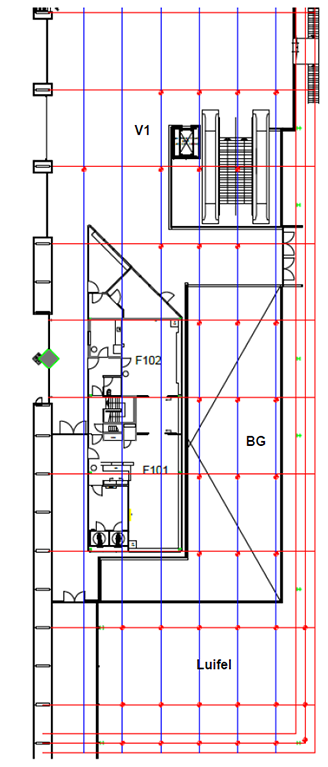
Figure 5: Suspension points at Entrance F
Height suspension point:
ground floor - height = 9.50 m
first floor - height = 7.50 m
Entrance F consists of a shed roof and a foyer. Vertical rigging is possible at the locations indicated in Figure 5.
In the shed roof, vertical rigging is possible from the lower part of the 2D and 3D frameworks. In the foyer, vertical rigging is allowed from the I-frame at less than 50 cm from the 2D framework.
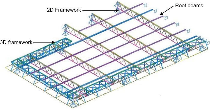
Figure 6: 3D model entrance area F
|
Vertical rigging (straight)
|
|
" |
Bridling (bridles)
|
|
Snowfall
|
Requirements for attachment to the roof construction
 |
Note: |
Article 7 - Park Foyer
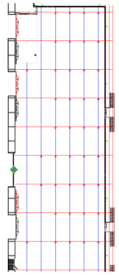
Figure 7: Park Foyer suspension points
Height suspension point:
height = 5.60 m
In the Park Foyer vertical rigging is permitted from eyes in the ceiling. There are a total of 38 possible suspension points (see Figure 7).
|
Vertical rigging (straight)
|
|
" |
Bridling (bridles)
|
|
Snowfall
|
Requirements for attachment to the roof construction
|
Note: |
Article 8 - Entrance K
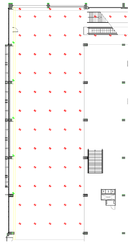
Figure 8: Suspension points in Entrance K
Height suspension point:
height = 7.35 m
Vertical rigging is allowed from the eyes in the ceiling in Entrance K. There are a total of 69 possible suspension points (see figure 8). Green dots represent 5 additional suspension points.
|
Vertical rigging (straight)
|
|
" |
Bridling (bridles)
|
|
Snowfall
|
Article 9 - Hall 1
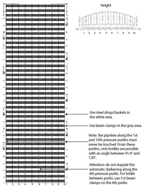
Figure 9: Suspension points in Hall 1
In Hall 1, rigging is allowed from the steel frames (see Figure 9). The steel frame connects 39 bow trusses together. Each bow truss has a maximum rigging load of 8,000 kg. The load must be distributed in accordance with Table 1. With maximum loads there are 480 possible suspension points.
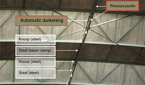
Figure 10: Steel frame in roof construction of Hall 1
| Table 1: Maximum load and distribution of weight in Hall 1 * 1 / 2 / 3 / 4 | |||
| On the member | On the joint | Total weight per bow truss | |
Vertical |
Max. 650 kg | Max. 650 kg | 8.000 kg |
Bridling (bridles) |
Max. 300 kg per bridle and max. 300 kg vertical load per member |
Max. 650 kg per bridle and max. 650 kg vertical load per joint |
|
Snowfall (between 5 and 10 cm) |
Total weight restriction per bow truss |
Total weight restriction per bow truss |
4.000 kg |
Snowfall (more than 10 cm) |
No rigging possible | No rigging possible | 0 kg |
| 1 A member is the part of the steel frame between two joints (see figure 10). 2 A joint is where two parts of the steel frame are connected to the bow truss (see figure 11). 3 The maximum load may be distributed between one or more suspension points. 4 If a member and an adjacent joint are loaded, the load on the member must be added to the load on the joint. The total weight must never exceed the maximum load for the joint. |
|||
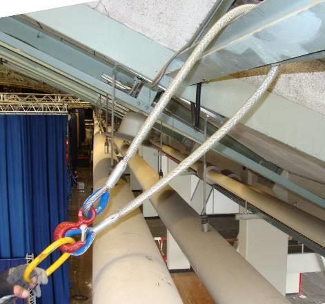
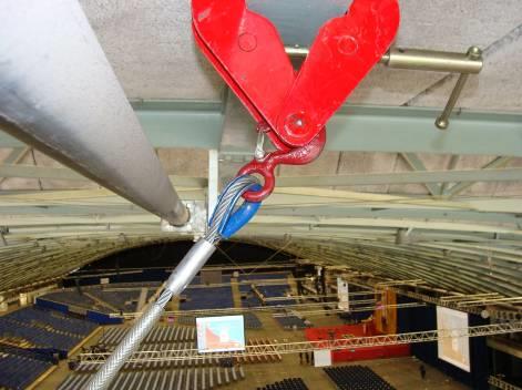
Requirements for attachment to the roof construction
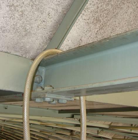 |
Steel sling at joint. |
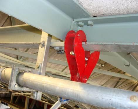 |
Beam clamp at joint. |
 |
Note: Note: Only 2-point bridles may be suspended from the 1st and 10th steel frames (above the balconies), at an angle of between 91.6° and 120°. |
 |
Note: : In order to protect the automatic blackout: Use a beam clamp on the 5th and 6th steel frame for 2-point bridles (bridles) between the 6th steel frame. |
Article 10 - Hall 2
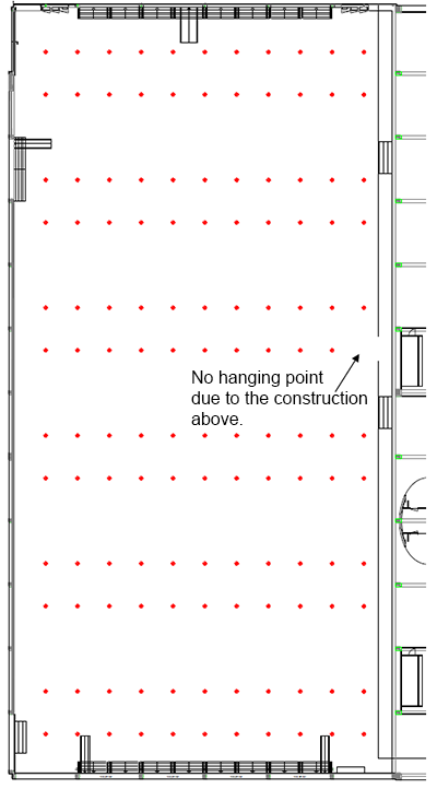
Figure 11: Suspension points in Hall 2
Height suspension points:
height = 7.35 m
In Hall 2, vertical rigging is allowed from the joints of the longitudinal girders. There are a total of 131 possible suspension points (see figure 11). The maximum permissible load is shown in table 2.
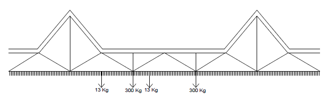
Figure 12: Joints in Hall 2
| Table 2: Maximum load and distribution of weight in Hall 2 * 1 / 2 | ||
| On the member | On the joint | |
Vertical |
13 kg | 300 kg |
Bridling (bridles) |
Not allowed | Not allowed |
Snowfall (more than 5 cm) |
No rigging possible | No rigging possible |
| 1 A member is the horizontal connection between two joints. 2 If a member and an adjacent joint are loaded, the load on the member must be added to the load on the joint. The total weight must never exceed the maximum load for the joint. |
||
Requirements for attachment to the roof construction
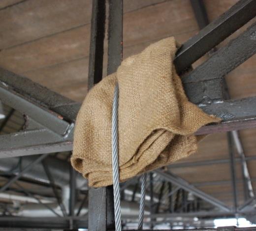 |
Between diagonal and vertical member with jute protection (burlap). |
Article 11 - Hall 3
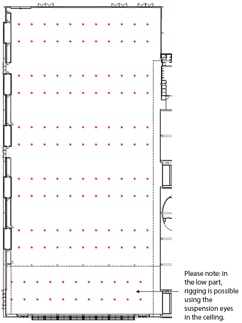
Figure 13: Suspension points in Hall 3
Height suspension points:
lower part = 8.00 m
higher part = 10.00 m
In Hall 3, vertical rigging is allowed from the joints of the longitudinal girders. There are a total of 132 possible suspension points (see figure 12). The maximum permissible load is shown in table 3.
Figure 14: Joints in Hall 3
| Table 3: Maximum load and distribution of weight in Hall 3 * 1 / 2 | ||
| On the member | On the joint and suspension eyes |
|
Vertical |
13 kg | 300 kg |
Bridling (bridles) |
Not allowed | Not allowed |
Snowfall (more than 5 cm) |
No rigging possible | No rigging possible |
| 1 A member is the horizontal connection between two joints 2 If a member and an adjacent joint are loaded, the load on the member must be added to the load on the joint. The total weight must never exceed the maximum load for the joint. |
||
Requirements for attachment to the roof construction
|
Between diagonal and vertical member with jute protection (burlap). |
 |
Suspension points in the lower part of the hall. |
Article 12 - Hall 4
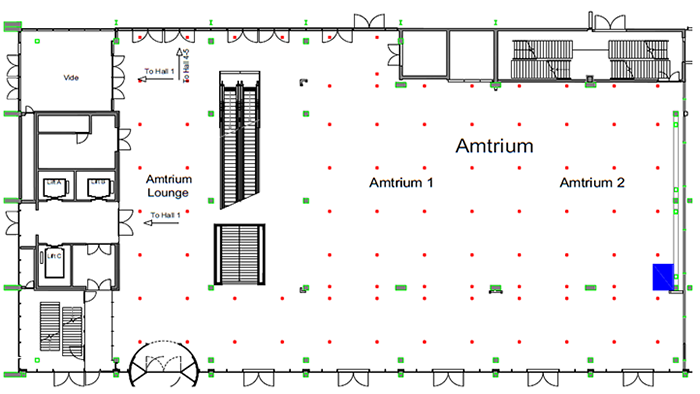
Figure 15: Suspension points Amtrium ground floor
Height suspension points:
4.95 m
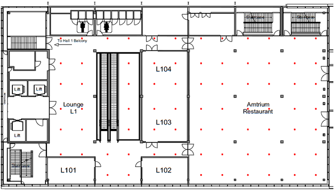
Figure 16: Suspension points Amtrium firstfloor
Height suspension points:
4.00 m
In the Amtrium, vertical rigging is possible from suspension eyes in the ceiling at the locations indicated (see Figure 15). There are a total of 69 possible suspension points on the ground floor and a total of 74 possible suspension points on the first floor.
|
Vertical rigging (straight)
|
|
" |
Bridling (bridles)
|
|
Snowfall
|
Suspension points
 |
 |
Article 13 - Hall 5
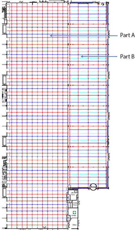
Figure 17: Suspension points in Hall 5
Height suspension points:
height = 10.00 m
Hall 5 consists of two parts. The old building (part A) and the new building (part B). Both have separate loads from the roof.
Part A & B
In Hall 5 part A, vertical rigging is allowed at the joints. There are a total of 484 possible suspension points (see Figure 17: Suspension points in Hall 5).
In Hall 5 part B vertical rigging is allowed at the joints. In total there are 140 possible suspension points (see Figure 17: Suspension points in Hall 5).
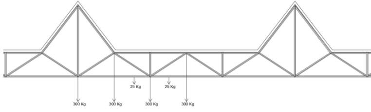
Figure 18: Joints in Hall 5
| Table 4A: Maximum load and distribution of weight in Hall 5A * 1 / 2 / 3 | ||
| On the member | On the joint | |
Vertical |
25 kg | 300 kg |
Bridling (bridles) |
Not allowed | Not allowed |
Snowfall (more than 5 cm) |
No rigging possible | No rigging possible |
| 1 A member is the horizontal connection between two joints. 2 If a member and an adjacent joint are loaded, the load on the member must be added to the load on the joint. The total weight must never exceed the maximum load for the joint 3 If a high or low joint is used, the load in the adjacent low joint should be reduced proportionally. Two joint next to each other may add up to a maximum of 300 kg. |
||
| Table 4B: Maximum load and distribution of weight in Hall 5B * 1 / 2 / 3 | ||
| On the member | On the joint | |
Vertical |
25 kg | 750 kg |
Bridling (bridles) |
Not allowed | Not allowed |
Snowfall (more than 5 cm) |
No rigging possible | No rigging possible |
| 1 A member is the horizontal connection between two joints. 2 If a member and an adjacent joint are loaded, the load on the member must be added to the load on the joint. The total weight must never exceed the maximum load for the joint 3 If a high or low joint is used, the load in the adjacent low joint should be reduced proportionally. Two joint next to each other may add up to a maximum of 300 kg. |
||
Requirements for attachment to the roof construction
|
Between diagonal and vertical member with jute protection (burlap). |
Article 14 - Hall 6
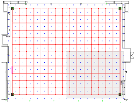
Figure 19: Suspension points in Hall 6
In Hall 6, rigging is allowed from the bottom part and the upper part of the 3-dimensional framework. In order to make maximum use of Hall 6, it has been divided into 4 notional 'rigging sections' (see figure 19). Each section area has a maximum suspension load of 22,500 kg. The weight is to be distributed as follows:
| Table 6: Distribution of weight on the members * 1 / 2 / 3 / 4 / 5 | |||
| Total rigging load per section |
up to 2,500 kg | 2,500 - 5,000 kg | 5,000 - 12,500 kg |
Vertical (upper or lower part) |
Max. 300 kg per member | Max. 300 kg per member | Max. 250 kg per member |
Bridling (upper or lower part) |
Max. 300 kg per bridle and max. 150 kg vertical load per member |
Max. 250 kg per bridle and max. 125 kg vertical load per member |
Max. 250 kg per bridle and max. 125 kg vertical load per member |
Snowfall (more than 5 cm) |
No restriction | No restriction | Max. 150 kg per member Max. 150 kg per bridle and Max. 75 kg vertical load per member |
| 1 A member forms part of the upper or lower part between two joints. 2 The maximum load may be distributed between one or more suspension points. 3 Suspension is not allowed around the lighting fixtures under the members (see CAD drawing). 4 If a member in the upper part and an adjacent member in the lower part are used at the same time, the maximum permissible weight for these members will be halved. 5 If a member and an adjacent joint are loaded, the load on the member must be added to the load on the joint. The total weight must never exceed the maximum load for the joint. |
|||
| Table 7: Distribution of weight on joints * 1 / 2 / 3 / 4 | |||
| Total rigging load per section |
up to 2,500 kg | 2,500 - 5,000 kg | 5,000 - 12,500 kg |
Vertical (upper or lower part) |
Max. 600 kg per joint | Max. 500 kg per joint | Max. 300 kg per joint |
Bridling bridles (upper or lower part) |
Max. 1.200 kg per bridle and max. 600 kg vertical load per joint |
Max. 1.000 kg per bridle and max. 500 kg vertical load per joint |
Max. 600 kg per bridle and max. 300 kg vertical load per joint |
Snowfall (more than 5 cm) |
No restriction |
No restriction |
Max. 150 kg per joint Max. 300 kg per bridle and Max. 150 kg vertical load per joint |
| 1 Suspension is not allowed around the lighting fixtures under the joints (see CAD drawing). 2 If a joint in the upper part and an adjacent joint in the lower part are used at the same time, the maximum permissible weight for these joints will be halved. 3 If a member and an adjacent joint are loaded, the load on the member must be added to the load on the joint. The total weight must never exceed the maximum load for the joint. 4 There are rules which apply to suspension from the joints (see Appendix II). |
|||
Requirements for attachment to the roof construction
 |
Through the centre of the joint. Between lower cross truss and cross diagonals. Note: |
 |
Through the centre of the joint. Between upper cross truss and cross diagonals. Note: |
Article 15 - Hall 7
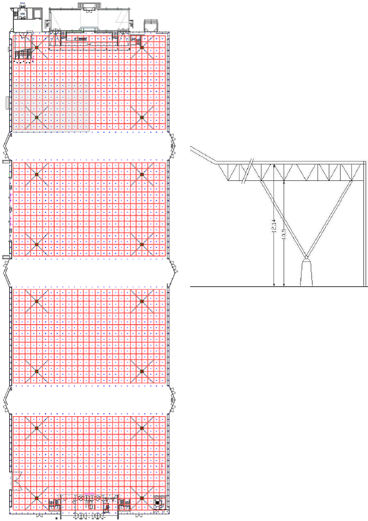
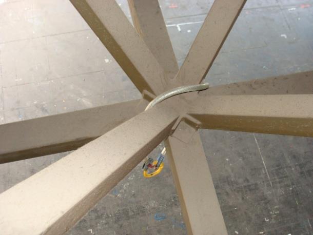
Figure 20: Suspension points in Hall 7
Height suspension points:
height = 10.40 m
Note:
The figure above shows the bottom edge and the nodes in the top edge of the three-dimensional truss.
In Hall 7, rigging is allowed from the bottom part and the upper part of the 3-dimensional framework. In order to make maximum use of Hall 7, it has been divided into 16 notional 'rigging sections' (see figure 20). Each section area has a maximum suspension load of 25,000 kg. The weight is to be distributed as follows:
| Table 8: Distribution of weight on the members * 1 / 2 / 3 / 4 / 5 | |||
| Total rigging load per section |
up to 6,250 kg | 6,250 - 12,500 kg | 12,500 - 25,000 kg |
Vertical (upper or lower part) |
Max. 300 kg per member | Max. 300 kg per member | Max. 250 kg per member |
Bridling (upper or lower part) |
Max. 300 kg per bridle and max. 150 kg vertical load per member |
Max. 250 kg per bridle and max. 125 kg vertical load per member |
Max. 250 kg per bridle and max. 125 kg vertical load per member |
Snowfall (more than 5 cm) |
No restriction | No restriction | Max. 150 kg per joint Max. 150 kg per bridle and Max. 75 kg vertical load per member |
| 1 A member forms part of the upper or lower part between two joints. 2 The maximum load may be distributed between one or more suspension points. 3 Suspension is not allowed around the lighting fixtures under the members (see CAD drawing). 4 If a member in the upper part and an adjacent member in the lower part are used at the same time, the maximum permissible weight for these members will be halved. 5 If a member and an adjacent joint are loaded, the load on the member must be added to the load on the joint. The total weight must never exceed the maximum load for the joint. |
|||
| Table 9: Distribution of weight on joints * 1 / 2 / 3 / 4 | |||
| Total rigging load per section |
up to 6,250 kg | 6,250 - 12,500 kg | 12,500 - 25,000 kg |
Vertical (upper or lower part) |
Max. 600 kg per joint | Max. 500 kg per joint | Max. 300 kg per joint |
Bridling bridles (upper or lower part) |
Max. 1.200 kg per bridle and Max. 600 kg vertical load per joint |
Max. 1.000 kg per bridle and Max. 500 kg vertical load per joint Max. 500 kg vertical load per joint |
Max. 600 kg per bridle and max. 300 kg vertical load per joint |
Snowfall (more than 5 cm) |
No restriction |
No restriction |
Max. 150 kg per joint Max. 300 kg per bridle and max. 150 kg vertical load per joint |
| 1 Suspension is not allowed around the lighting fixtures under the joints (see CAD drawing). 2 If a joint in the upper part and an adjacent joint in the lower part are used at the same time, the maximum permissible weight for these joints will be halved. 3 If a member and an adjacent joint are loaded, the load on the member must be added to the load on the joint. The total weight must never exceed the maximum load for the joint. 4 There are rules which apply to suspension from the joints (see appendix II). |
|||
Requirements for attachment to the roof construction
|
Through the centre of the joint. Between lower cross truss and cross diagonals. Note: |
|
|
Through the centre of the joint. Between upper cross truss and cross diagonals. Note: |
Article 16 - Hall 8
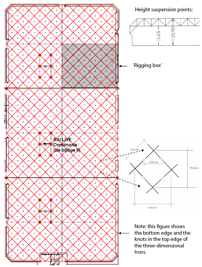
Figure 21:
Suspension points in Hall 8
In Hall 8, rigging is allowed from the bottom part and the upper part of the 3-dimensional framework. In order to make maximum use of Hall 8, it has been divided into 12 notional 'rigging sections' (see figure 21). Each section area has a maximum suspension load of 22,500 kg. The weight is to be distributed as follows:
| Table 10: Distribution of weight on the members * 1 / 2 / 3 / 4 / 5 / 6 | ||
| Total rigging load per section |
up to 10,000 kg | 10,000 - 22,500 kg |
Vertical (upper or lower part) |
Max. 500 kg per member | Max. 500 kg per member |
Bridling (upper or lower part) |
Max. 500 kg per bridle and max. 250 kg vertical load per member |
Max. 400 kg per bridle and max. 200 kg vertical load per member |
Snowfall (more than 5 cm) |
Max. 160 kg per member Max. 250 kg per bridle and Max. 125 kg vertical load per member |
More than 10,000 kg per area not possible See requirements under 10,000 kg |
| 1 A member forms part of the upper or lower part between two joints. 2 The maximum load may be distributed between one or more suspension points. 3 Suspension is not allowed around the lighting fixtures under the members (see CAD drawing). 4 If a member in the upper part and an adjacent member in the lower part are used at the same time, the maximum permissible weight for these members will be halved. 5 If a member and an adjacent joint are loaded, the load on the member must be added to the load on the joint. The total weight must never exceed the maximum load for the joint. 6 If the RAI LIVE screens are suspended in their construction, restrictions apply (see Appendix II). |
||
| Tabel 11: Gewichtsverdeling op knopen * 1 / 2 / 3 / 4 / 5 / 6 | |||
| Total rigging load per section |
up to 10,000 kg | 10,000 - 22,500 kg | |
Vertical (upper or lower part) |
Max. 900 kg per joint | Max. 900 kg per joint | |
Bridling (upper or lower part) |
Max. 1,800 kg per bridle and Max. 900 kg vertical load per joint |
Max. 1,800 kg per bridle and Max. 900 kg vertical load per joint |
|
Snowfall (more than 5 cm) |
Max. 450 kg per joint Max. 900 kg per bridle and Max. 450 kg vertical load per joint |
More than 10,000 kg per area not possible See requirements under 10,000 kg |
|
| 1 The maximum load may be distributed between one or more suspension points per member. 2 If a joint in the upper part and an adjacent joint in the lower part are used at the same time, the maximum permissible weight for these joints will be halved. 3 If a member and an adjacent joint are loaded, the load on the member must be added to the load on the joint. The total weight must never exceed the maximum load for the joint. 4 There are rules which apply to suspension from the joints. 5 If the RAI LIVE screens are suspended in their construction, restrictions apply (see Appendix II). 6 Rigging is not permitted from the eyes under the joints. |
|||
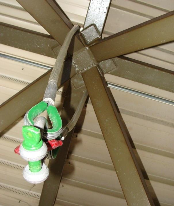
Requirements for attachment to the roof construction
 |
Through the centre of the joint. Between lower cross truss and cross diagonals. Note: |
 |
Through the centre of the joint. Between lower cross truss and cross diagonals. |
 |
Note: |
Article 17 - Hall 9
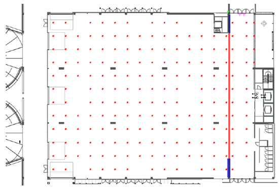
Figure 22: Rigging options in Hall 9 (MFP)
Height suspension points:
height hall = 5.70 m
height corridor = 4.40 m
In Hall 9 (MFP), vertical rigging is possible from suspension eyes in the ceiling. There are a total of 204 possible suspension points (see figure 22). 180 suspension points are located at a height of 5,70 metres (hall) and 24 suspension points at a height of 4.40 metres (corridor).
|
Vertical rigging (straight)
|
|
" |
Bridling (bridles)
|
|
Snowfall
|
Suspension point
Article 18 - Hall 10
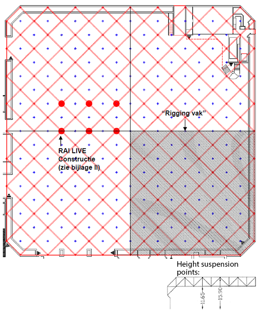
Figure 23: Rigging options in Hall 10
Note:
The figure above shows the bottom edge and the nodes in the top edge of the three-dimensional truss.
In Hall 10, rigging is allowed from the bottom part and the upper part of the 3-dimensional framework. In order to make maximum use of Hall 9, it has been divided into 4 notional 'rigging sections' (see figure 23). Each section area has a maximum suspension load of 22,500 kg. The weight is to be distributed as follows:
| Table 12: Distribution of weight on the members * 1 / 2 / 3 / 4 / 5 / 6 | ||
| Total rigging load per section |
up to 10,000 kg | 10,000 - 22,500 kg |
Vertical (upper or lower part) |
Max. 500 kg per member | Max. 500 kg per member |
Bridling (upper or lower part) |
Max. 500 kg per bridle and Max. 250 kg vertical load per member |
Max. 400 kg per bridle and Max. 200 kg vertical load per member |
Snowfall (meer dan 5 cm) |
Max. 160 kg per member Max. 250 kg per bridle and max. 125 kg vertical load per member |
More than 10,000 kg per area not possible. See requirements under 10,000 kg |
| 1 A member forms part of the upper or lower part between two joints. 2 The maximum load may be distributed between one or more suspension points. 3 Suspension is not allowed around the lighting fixtures under the members (see CAD drawing). 4 If a member in the upper part and an adjacent member in the lower part are used at the same time, the maximum permissible weight for these members will be halved. 5 If a member and an adjacent joint are loaded, the load on the member must be added to the load on the joint. The total weight must never exceed the maximum load for the joint. 6 If the RAI LIVE screens are suspended in their construction, restrictions apply (see Appendix II). |
||
| Table 13: Distribution of weight on joints * 1 / 2 / 3 / 4 / 5 / 6 | ||
| Total rigging load per section |
up to 10,000 kg | 10,000 - 22,500 kg |
Vertical (upper or lower part) |
Max. 900 kg per joint | Max. 900 kg per joint |
Bridling (upper or lower part) |
Max. 1.800 kg per bridle and Max. 900 kg vertical load per joint |
Max. 1.800 kg per bridle and Max. 900 kg vertical load per joint |
Snowfall (more than 5 cm) |
Max. 450 kg per joint Max. 900 kg per bridle and Max. 450 kg vertical load per joint |
More than 10,000 kg per area not possible See requirements under 10,000 kg |
| 1 The maximum load may be distributed between one or more suspension points per member. 2 If a joint in the upper part and an adjacent joint in the lower part are used at the same time, the maximum permissible weight for these joints will be halved. 3 If a member and an adjacent joint are loaded, the load on the member must be added to the load on the joint. The total weight must never exceed the maximum load for the joint. 4 There are rules which apply to suspension from the joints. 5 If the RAI LIVE screens are suspended in their construction, restrictions apply (see Appendix II). 6 Rigging is not permitted from the eyes under the joints. |
||
Requirements for attachment to the roof construction
|
Through the centre of the joint. Between lower cross truss and cross diagonals. Note: |
|
Through the centre of the joint. Between lower cross truss and cross diagonals. |
|
Note: |
Article 19 - Hall 11
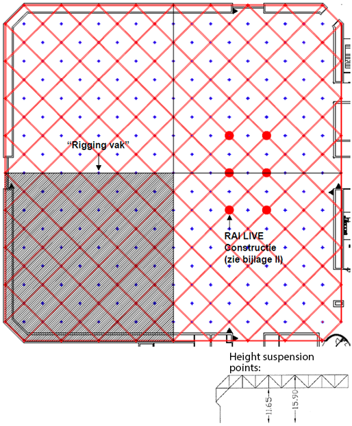
Figure 24: Rigging options in Hall 11
Note:
The figure above shows the bottom edge and the nodes in the top edge of the three-dimensional truss.
In Hall 11, rigging is allowed from the bottom part and the upper part of the 3-dimensional framework. In order to make maximum use of Hall 10, it has been divided into 4 notional 'rigging sections' (see figure 24). Each section area has a maximum suspension load of 22,500 kg. The weight is to be distributed as follows:
| Table 14: Distribution of weight on the members * 1 / 2 / 3 / 4 / 5 / 6 | ||
| Total rigging load per section |
up to 10,000 kg | 10,000 - 22,500 kg |
Vertical (upper or lower part) |
Max. 500 kg per member | Max. 500 kg per member |
Bridling (upper or lower part) |
Max. 500 kg per bridle and max. 250 kg vertical load per member |
Max. 400 kg per bridle and max. 200 kg vertical load per member |
Snowfall (more than 5 cm) |
Max. 160 kg per member Max. 250 kg per bridle and Max. 125 kg vertical load per member |
More than 10,000 kg per area not possible See requirements under 10,000 kg |
| 1 A member forms part of the upper or lower part between two joints. 2 The maximum load may be distributed between one or more suspension points. 3 Suspension is not allowed around the lighting fixtures under the members (see CAD drawing). 4 If a member in the upper part and an adjacent member in the lower part are used at the same time, the maximum permissible weight for these members will be halved. 5 If a member and an adjacent joint are loaded, the load on the member must be added to the load on the joint. The total weight must never exceed the maximum load for the joint. 6 If the RAI LIVE screens are suspended in their construction, restrictions apply (see Appendix II). |
||
| Table 15: Distribution of weight on joints * 1 / 2 / 3 / 4 / 5 / 6 | ||
| Total rigging load per section |
up to 10,000 kg | 10,000 - 22,500 kg |
Vertical (upper or lower part) |
Max. 900 kg per joint | Max. 900 kg per joint |
Bridling (upper or lower part) |
Max. 1.800 kg per bridle and max. 900 kg vertical load per joint |
Max. 1.800 kg per bridle and max. 900 kg vertical load per joint |
Snowfall (more than 5 cm) |
Max. 450 kg per joint Max. 900 kg per bridle and Max. 450 kg vertical load per joint |
More than 10,000 kg per area not possible See requirements under 10,000 kg |
| 1 The maximum load may be distributed between one or more suspension points per member. 2 If a joint in the upper part and an adjacent joint in the lower part are used at the same time, the maximum permissible weight for these joints will be halved. 3 If a member and an adjacent joint are loaded, the load on the member must be added to the load on the joint. The total weight must never exceed the maximum load for the joint. 4 There are rules which apply to suspension from the joints. 5 If the RAI LIVE screens are suspended in their construction, restrictions apply (see Appendix II). 6 Rigging is not permitted from the eyes under the joints. |
||
Requirements for attachment to the roof construction
|
Through the centre of the joint. Between lower cross truss and cross diagonals. Note: |
|
Through the centre of the joint. Between lower cross truss and cross diagonals. |
|
Note: |
Article 20 - Hall 12
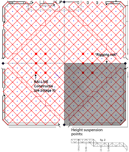
Figure 25: Rigging options in Hall 12
Note:
The figure above shows the bottom edge and the nodes in the top edge of the three-dimensional truss.
In Hall 12 rigging is allowed from the bottom part and the upper part of the 3-dimensional framework. In order to make maximum use of Hall 12, it has been divided into 4 notional 'rigging sections' (see figure 25). Each section area has a maximum suspension load of 22,500 kg. The weight is to be distributed as follows:
| Distribution of weight on the members * 1 / 2 / 3 / 4 / 5 / 6 | ||
| Total rigging load per section |
up to 22,500 kg | 22,500 - 50,000 kg |
Vertical (upper or lower part) |
Max. 500 kg per member | Max. 500 kg per member |
Bridling (upper or lower part) |
Max. 500 kg per bridle and max. 250 kg vertical load per member |
Max. 400 kg per bridle and max. 200 kg vertical load per member |
Snowfall (more than 5 cm) |
Max. 160 kg per member Max. 250 kg per bridle and Max. 125 kg vertical load per member |
More than 10,000 kg per area not possible See requirements under 10,000 kg |
| 1 A member forms part of the upper or lower part between two joints. 2 The maximum load may be distributed between one or more suspension points. 3 Suspension is not allowed around the lighting fixtures under the members (see CAD drawing). 4 If a member in the upper part and an adjacent member in the lower part are used at the same time, the maximum permissible weight for these members will be halved. 5 If a member and an adjacent joint are loaded, the load on the member must be added to the load on the joint. The total weight must never exceed the maximum load for the joint. 6 If the RAI LIVE screens are suspended in their construction, restrictions apply (see Appendix II). |
||
| Table 17: Distribution of weight on joints * 1 / 2 / 3 / 4 / 5 / 6 | ||
| Total rigging load per section |
up to 22,500 kg | 22,500 - 50,000 kg |
Vertical (upper or lower part) |
Max. 900 kg per joint | Max. 900 kg per joint |
Bridling (upper or lower part) |
Max. 1.800 kg per bridle and Max. 900 kg vertical load per joint |
Max. 1.800 kg per bridle and Max. 900 kg vertical load per joint |
Snowfall (more than 5 cm) |
Max. 450 kg per joint Max. 900 kg per bridle and Max. 450 kg vertical load per joint |
More than 10,000 kg per area not possible See requirements under 10,000 kg |
| 1 The maximum load may be distributed between one or more suspension points per member. 2 If a joint in the upper part and an adjacent joint in the lower part are used at the same time, the maximum permissible weight for these joints will be halved. 3 If a member and an adjacent joint are loaded, the load on the member must be added to the load on the joint. The total weight must never exceed the maximum load for the joint. 4 There are rules which apply to suspension from the joints (see next page). 5 If the RAI LIVE screens are suspended in their construction, restrictions apply (see Appendix II). 6 Rigging is not permitted from the eyes under the joints. |
||
Requirements for attachment to the roof construction
|
Through the centre of the joint. Between lower cross truss and cross diagonals. Note: |
|
Through the centre of the joint. Between lower cross truss and cross diagonals. |
|
Note: |
Article 21 - Hall 13
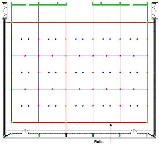
Rails
The thickened lines represent rails.
Suspension points can be made in these rails at the specified locations
with specially developed lifting equipment, provided that
no partition has been placed in the rails.
These are available from the Technical Service Department.
Figure 26: Suspension points in the Elicium Ballroom
Height suspension points:
height red = 6.80 m
height green = 6.80 m
height blue = 8.70 m
In the Elicium Ballroom, vertical rigging is possible from suspension eyes in the ceiling. There are a total of 92 possible suspension points. 62 suspension points are located at a height of 6.80 metres (see red dots in figure 26) and 30 suspension points at a height of 8.70 metres (see blue dots in figure 26).
Note: Rails are installed in the roof (see Figure 26). Specially designed suspension eyes can be fitted at the locations indicated (green dots), provided that there is no partition wall fitted to the rails. These suspension eyes are to be requested via the Account Manager of the RAI.
|
Vertical rigging (straight)
|
|
" |
Bridling (bridles)
|
|
Snowfall
|
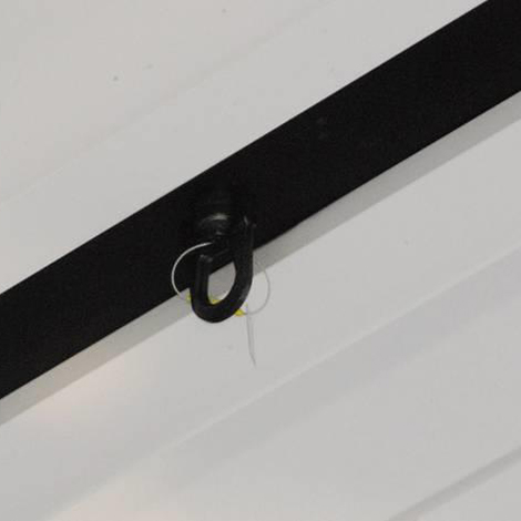
Requirements for attachment to the roof construction
Green suspension points
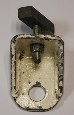 |
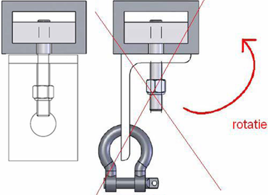 Note: The rail eyes must be positioned on the rail at right angles. |
Red suspension points
 |
 |
Blue suspension points
|
|
Article 22 - Auditorium Lounge and Onyx Lounge
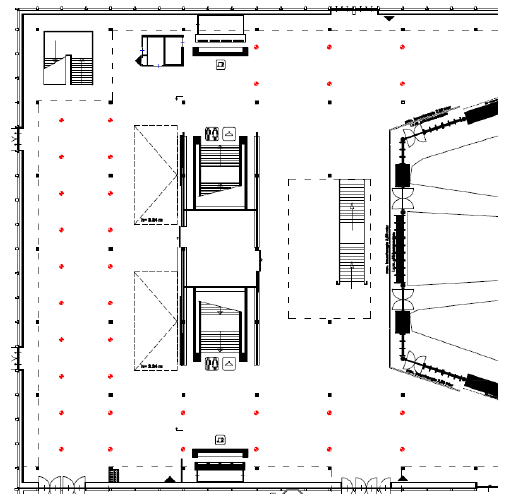
Figure 27: Auditorium Lounge and Onyx Lounge suspension points
Height suspension points:
height = 3.74 m
Between suspension points
↔ = 7.50 m
↨ = 3,75 m
In the Auditorium Lounge and Onyx Lounge vertical rigging is permitted from eyes in the ceiling. There are a total of 34 possible suspension points (see figure 27).
|
Vertical rigging (straight)
|
|
" |
Bridling (bridles)
|
|
Snowfall
|
Requirements for attachment to the roof construction
|
|
Note: |
Article 23 - Upper Lounge and Emerald Lounge
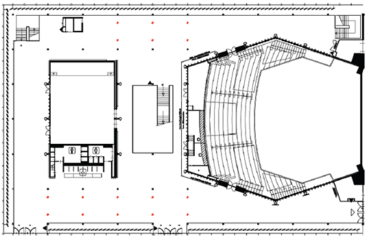
Figure 28: Upper Lounge and Emerald Lounge suspension points
Height suspension points:
height = 3.74 m
In the Upper Lounge and Emerald Lounge vertical rigging is allowed from eyes in the ceiling. There are a total of 16 possible suspension points (see figure 28).
|
Vertical rigging (straight)
|
|
" |
Bridling (bridles)
|
|
Snowfall
|
Requirements for attachment to the roof construction
|
|
Note: |
Article 24 - Diamond Lounge
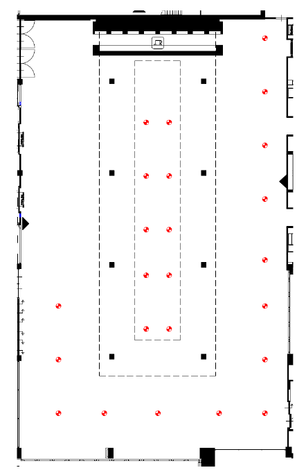
Figure 29: Suspension points in the Diamond Lounge
Height suspension points:
height = 3.50 m
In the Diamond Lounge, vertical rigging is allowed from eyes in the ceiling. There are a total of 24 suspension points in the Diamond Lounge (see figure 29).
|
Vertical rigging (straight)
|
|
" |
Bridling (bridles)
|
|
Snowfall
|
Requirements for attachment to the roof construction
|
|
Note: |
Article 25 - Europe Foyer 1 and 2
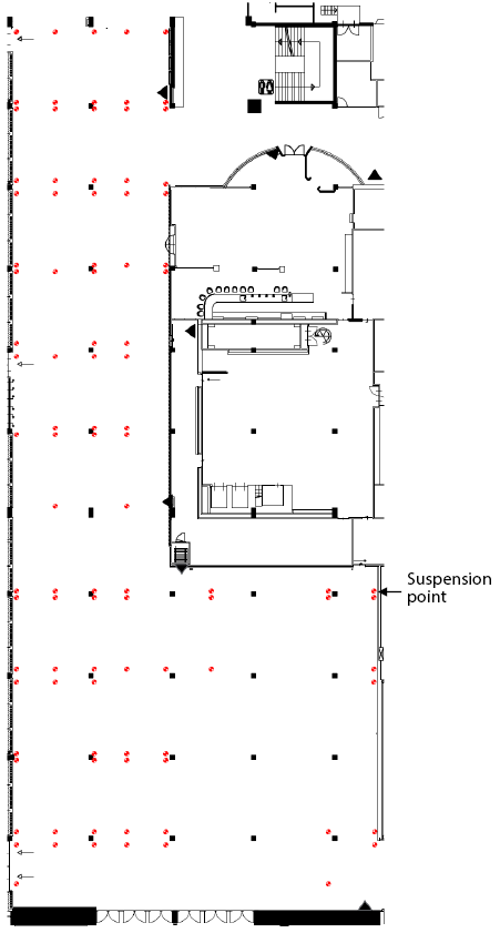
Figure 30: Rigging options in Europe Foyer 1 and 2
Height suspension points:
height = 3.10 m
In Europe Foyer 1 and 2 vertical rigging is allowed from eyes in the ceiling. There are a total of 96 possible suspension points (see figure 30). The fitting of own lifting eyes is not permitted.
|
Vertical rigging (straight)
|
|
" |
Bridling (bridles)
|
|
Snowfall
|
Article 26 - Room G102
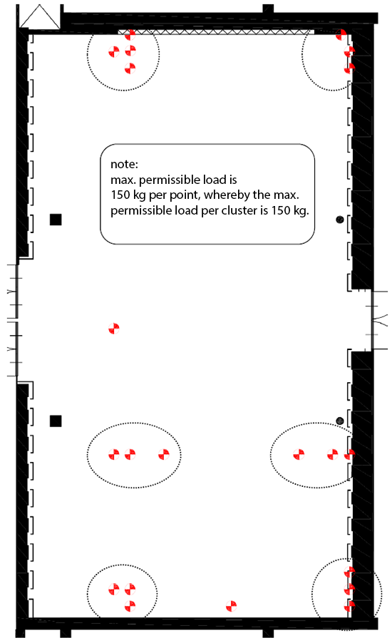
Figure 31: Suspension points in G102
In Room G102 there are 21 suspension points (see figure 31). The suspension points are to be used as follows:
|
Vertical rigging (straight)
|
|
" |
Bridling (bridles)
|
|
Snowfall
|
Requirements for attachment to the roof construction
|
|
Note: |
Article 27 - Room E103 - E108
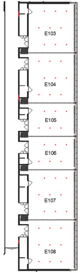
Figure 32: suspension points Room E 103-E 108
In Room E103, E104, E105, E106, E107 and E108 rigging is possible at the suspension points. The suspension points can be used as follows:
|
Vertical rigging (straight)
|
|
" |
Bridling (bridles)
|
|
Snowfall
|
Suspension point
Article 28 - Room ceiling Auditorium
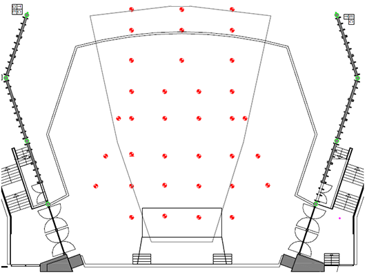
Figure 33: suspension points room ceiling Auditorium
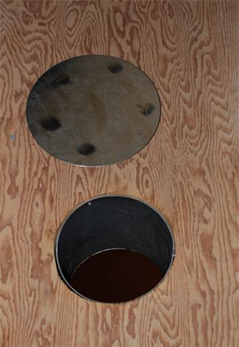
A total of 27,500 kg can be hung from the ceiling of the Auditorium. Rigging can only be done from the rafter constructions above the through holes in the ceiling (the points in the drawing).
Care must be taken when jacking up the hoists that they do not touch the ceiling (plasterboard). Make sure that the chains run vertically downwards when hanging and lifting.
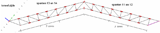
Figure 34: straight frames
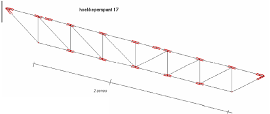
Figure 35: oblique frames
|
Vertical rigging
|
|
" |
Bridling (bridles)
|
|
Snowfall
|
Rafter at congress rolls
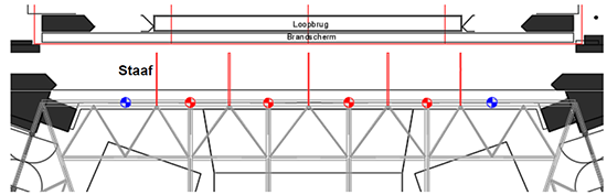
Figure 36: Location of suspension points on rafter 19
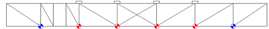
Figure 37: Side view rafter 19
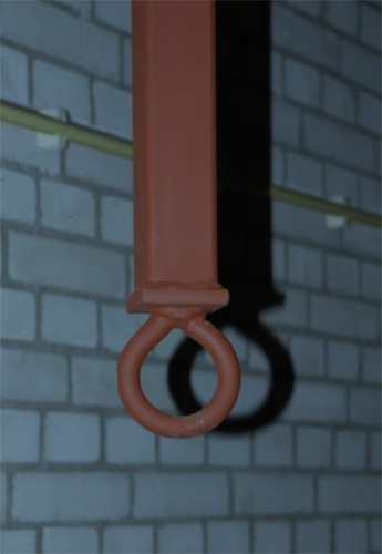
Vertical rigging is allowed on the rafter above the front stage (first room bridge). The ends of the rafter (blue points) are reserved for the Line array of the RAI. If the Line array is not suspended, a load of 1,000 Kg is possible here.
Rigging is not possible between the blue and red suspension points. Between the red suspension points, rigging is possible on the top and bottom rail. The maximum load between two suspension points may do not exceed the load of a single suspension point.
|
Vertical rigging (straight)
|
|
" |
Bridling (bridles)
|
|
Snowfall
|
Article 29 - Stage tower Auditorium
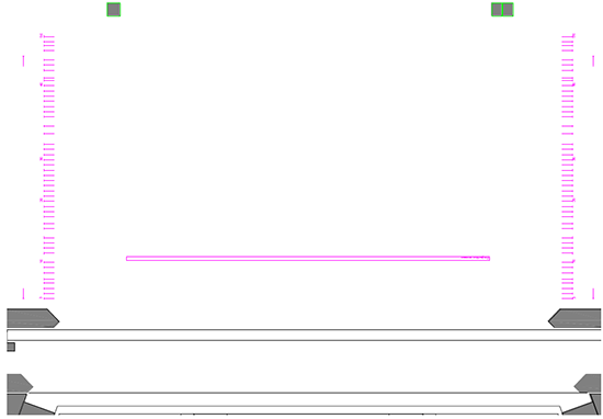
Figure 38: Fly system (theatrical rigging system), bar plan
Dimensions:
width bar = 20.40 m
max. bar height = 18.20 m
min. bar height = 0.30 m
max. speed = 1.80 m/s
rod diameter = 50 mm
Figure 38 shows the fly systems and the bars. The fly system is controlled by a BBH computer. The installation consists of 50 bars and 2 side bars. The total maximum load of the pulling wall is 25,000 kg.
|
Vertical rigging bars
|
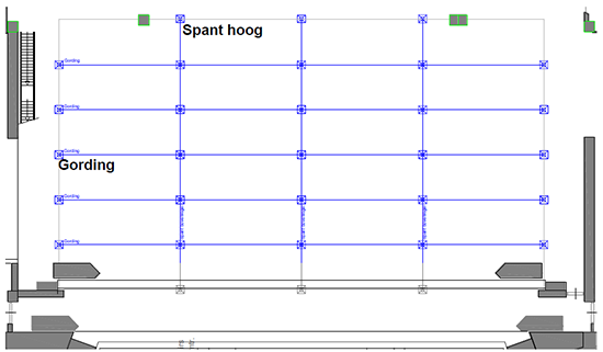
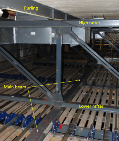
Figure 39: Roofconstruction high rafters ('Spant hoog') and Purling ('Gording')
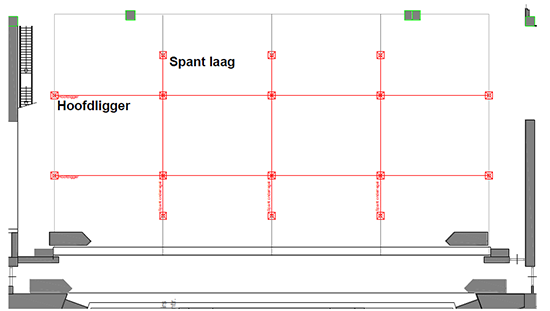
Figure 40: Roofconstruction lower rafters ('Spant laag') and main beam ('Hoofdligger')
Dimensions:
height high truss = 21.75 m
height low truss = 19.85 m
Figures 39 and 40 show the roof construction of the stage tower. The weight that can be hang from the roof construction, partly depends on the load in the bars.
The maximum load of the tower is 34,000 Kg. The snow load (9,000 Kg) and the used load in the bars needs to be dedected from the max. tower load.
The diagram below shows the load level of the fly system and what may additionally be hung from the roof construction.
| Bar load | 0 up to 50% 2 | 50 up to 75% 2 | 75 up to 100% 2 |
| Max. load per rafter per spant |
9,000 kg | 4,000 kg | 4,000 kg |
| The rafters ('spanten') (per member) 1 | |||
Vertical |
1,500 kg | 830 kg | 830 kg |
Bridling (bottom edge) |
500 kg | 500 kg | 500 kg |
Bridling (top edge) |
300 kg | 300 kg | 300 kg |
Snowfall |
No restrictions in case of snowfall | No restrictions in case of snowfall | No rigging |
| 1 A member is a part of the bottom or top edge between two joints. 2 Calculation maximum ceiling load = 25,000 kg (weight on the bars of the fly system) = maximum allowable. |
|||
| The purlins ('Gordingen') (between two joints) | |||
|
Vertical | Max. 750 kg 1 | |
|
Bridling | Max. 250 kg | |
|
Snowfall | No restrictions | |
| 1 Note: If bridals are used, the bridal load may not be exceeded when using simultaneous vertical rigging. | |||
| The main beam ('Hoofdligger') (between two joints) | |||
|
Vertical | Max. 3,000 kg 1 | |
|
Bridling | Max. 600 kg | |
|
Snowfall | No restrictions | |
| 1 Note: If bridals are used, the bridal load may not be exceeded when using simultaneous vertical rigging. | |||
Rafter construction
Article 30 - Forum
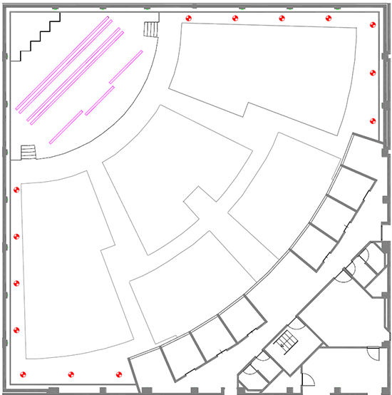
Figure 41: Suspension points Forum room
Figure 41 shows the suspension points in the Forum room. In addition to these suspension points, there are 3 more free bars that can be used above the stage, the front of which is a shared bar.
|
Vertical rigging suspension points
|
|
Vertical rigging bars
|
|
" |
Bridling (bridles) (bridles)
|
|
Snowfall
|
Ceiling 'through hole' and suspension point.
 |
 |
Appendix I: Requirements for the rigging plan
The table below shows the format for the rigging plan to be submitted to the RAI. Send the rigging plan to the Accountmanager at the RAI Amsterdam. Incomplete rigging plans will not be assessed and therefore will not be approved. The RAI can provide an example of an acceptable rigging plan on request.
| Section of rigging plan | Requirements per section | By whom |
| 1. Lifting point plan (submit as dwg plus copy as pdf) |
Entered on CAD drawing from RAI Amsterdam * 1:
|
Responsible rigging company |
| 2. Calculated weight of the loads (submit as Excel sheet) |
Entered in the RAI Amsterdam rigging calculations format
|
Responsible rigging company |
| 3. Calculation of weight of bridles loads (submit as Excel sheet) |
Entered in the RAI Amsterdam rigging calculations format
|
Responsible rigging company |
| 4. Total weight of several suspension points on a truss part (submit as Excel sheet) |
Entered in the RAI Amsterdam rigging calculations format
|
Responsible rigging company |
| * 1 Each part of the building from this rigging manual has its own CAD drawing on which the possible suspension points are indicated. | ||
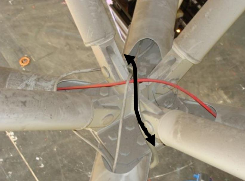
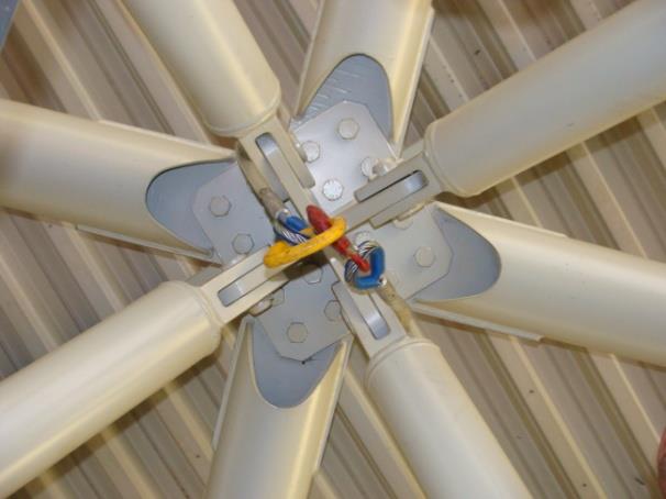
Appendix II: RAI LIVE restrictions Hall 8, 10, 11 and 12
|
In Halls 8, 10, 11 and 12 there is a suspended construction to which RAI LIVE information screens can be attached. If the screens are suspended in the construction, the following rigging restrictions apply:
Note: No restrictions apply if the screens are not suspended in the construction and the trolley beam is located between four suspension points (this location is indicated with a black arrow). |
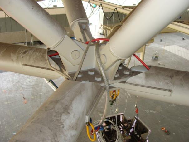
 |
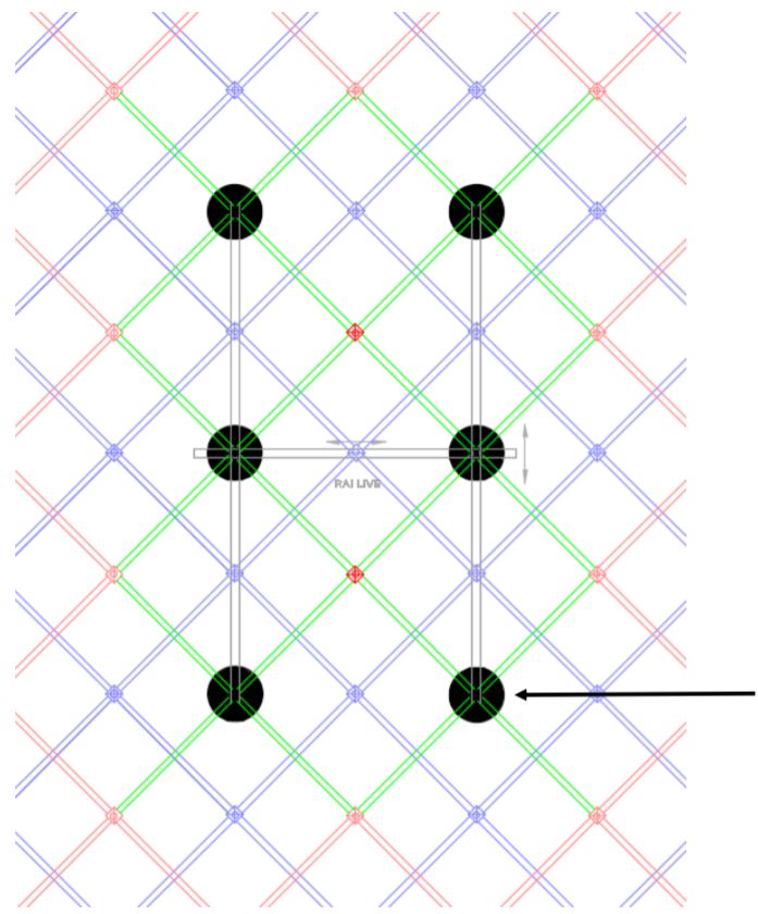
Figure 42: Area with rigging restriction around RAI LIVE construction
Rigging in the RAI ENG - Version 1.7 - 2021