Annex 4e - RAI Rigging Manual
Contents
1 Introduction
These guidelines set out where, and under which conditions, rigging may be carried out at RAI Amsterdam. For each location, the document describes where rigging is permitted and the maximum permissible load per suspension point, both for vertical rigging (straight) and for bridles.
If you wish to carry out rigging within our complex, the rigging party must submit a rigging plan to the RAI Account Manager for the relevant event or exhibition four weeks before the start of that event or exhibition. The required format and content of the rigging plan are described in this document. Each rigging plan is then assessed against the criteria set out in this document. You will receive an official response from RAI within no more than five working days, after which any required amendments can be made. A final version must be agreed two weeks before the start of the event or exhibition.
RAI reserves the right to amend this Rigging Manual (Rigging at RAI) at any time as a result of structural changes, new calculations, inspections or revised technical insights. It is solely the responsibility of the user to consult the most up-to-date version of the Rigging Manual (Rigging at RAI) on RAI.nl prior to each application. Any differences between versions may relate to both increased and reduced load capacities and permitted uses. RAI accepts no liability for damage or costs arising from the use of outdated information.
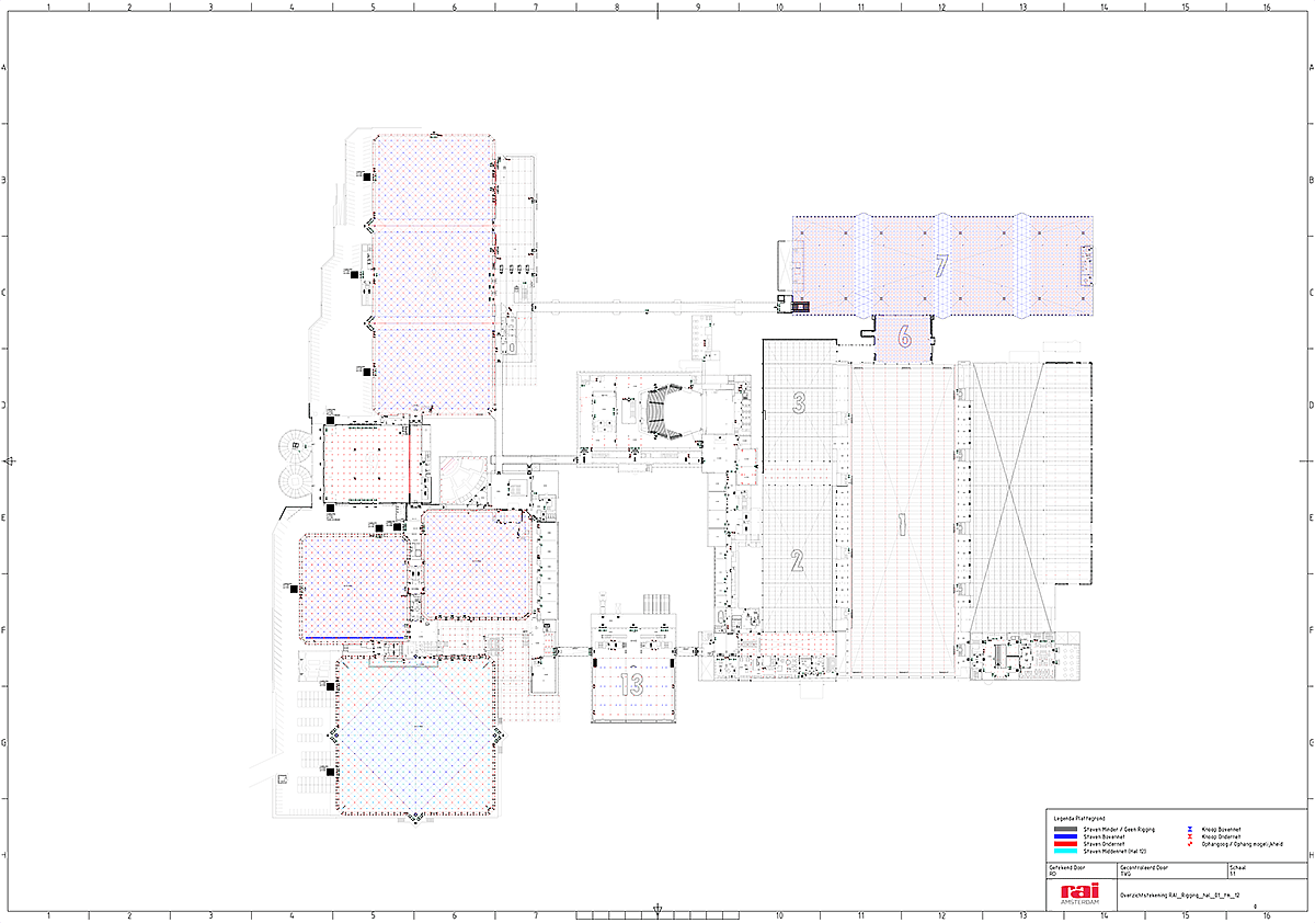
The floor plan of RAI Amsterdam is shown below (Figure 1). Each hall, entrance area and foyer has its own chapter, provided rigging is possible there.

2 Rigging Guidelines
For all decisions to be made, safety comes first. To be permitted to carry out rigging at RAI, the following conditions must be met:
Certification of company and personnel
- Rigging may only be undertaken by companies certified to VCA*, VCA**, OHSAS 18001 or ISO 45001.
- Each rigger present must hold the following:
- a valid VCA certificate (VCA-B or VCA-VOL).
- demonstrable certification in Elementary Lifting Techniques in the Entertainment Industry, exhibition rigging certificate or an equivalent qualification, such as a National Rigging Certificate (UK), Arena Rigging Certificate from ETCP (USA), Rigstar Rigging Certificate (USA), or a relevant VLPT rigging diploma (Germany).
- Where a mobile elevating work platform is used, the operator must hold a valid MEWP certificate. The rigger is responsible for ensuring that no third parties are present within their working area.
- Anyone working in a mobile elevating work platform must wear a full-body safety harness (EN361), attached by a safety lanyard (EN355) to the anchor point in the work basket.
- Persons in the vicinity of the mobile elevating work platform, including ground crew, must wear a helmet (EN397) within its operating area.
Rigging plan requirements
- Each executing rigging party must have a rigging plan approved by RAI. Appendix I describes how the rigging plan must be submitted to RAI. Your RAI Account Manager can also provide an example.
- Each building section described in this document has an associated AutoCAD drawing showing the available suspension points. A PDF printout of this drawing is included in Appendix II.
- The maximum permissible load stated in this manual must not be exceeded.
- For bridles, the internal angle must be less than 120 degrees.
- The maximum permissible load for bridles is based on two-leg bridles. For bridles, the force distribution at all points of application must be clearly calculated.
- Dynamic loads are not permitted without the explicit approval of a structural engineer appointed by RAI, at the expense of the client/contractor.
Rigging in practice
- Rigging may only be carried out in accordance with the approved plan; any changes must be agreed with the Daily Maintenance Manager.
- In the event of exceptionally high snow loads, RAI is authorised to require an already approved load to be reduced to an acceptable weight.
- The roof structure must not be damaged in any way.
- Fixed roof elements, such as light fittings, louvres, blackout mechanisms and drainage pipes, must not be struck during rigging.
Use of materials
- Rigging may only be carried out using materials that bear a CE marking.
For parties from outside the EU, the products must demonstrably comply with ASME or an equivalent standard.
- The materials must carry a WLL inscription or label.
- The maximum permissible load is 0.5 times the industrial WLL.
- The materials must be inspected at least once a year, and the inspection report must be available on request within 24 hours.
- The materials must be used in accordance with the manufacturer’s instructions.
Please note: The rigging party must be aware that RAI checks whether the suspension points have been installed in accordance with the guidelines and the rigging plan. If the agreed requirements are not met, RAI has the authority to reject the rigging. In the event of rejection, RAI shall not be liable for any damage or loss, including financial loss or reputational damage.
3 Halls
3.1 Hall 1


Table 1 - Maximum load and load distribution for members in Hall 1
| Rigging load on member 1,2,3 | |
| Total rigging load per arch truss | Up to 5,000 kg |
| Total rigging load on outer arch trusses (along the façade and Hall 6) |
Up to 2,500 kg |
|
Vertical direct (top and bottom chord) |
Maximum 650 kg per member |
|
Vertical bridle (top and bottom chord) |
Maximum 300 kg per bridle, subject to a maximum vertical load of 150 kg per member |
- A member is the part of the compression purlin between two node connections (see Figure 3).
- The maximum load may be distributed over one or more suspension points.
- If a member and a node are loaded next to each other, the member load must be added to the node load. The total weight must never exceed the maximum node load.
Table 2 - Maximum load and load distribution for nodes in Hall 1
| Rigging load on node 1,2,3 | |
| Total rigging load per arch truss | Up to 5,000 kg |
|
Total rigging laod on outer arch trusses (along the façade and Hall 6) |
Up to 2,500 kg |
|
Vertical direct (top and bottom chord) |
Maximum 650 kg per node |
|
Vertical bridle (top and bottom chord) |
Maximum 650 kg per bridle, subject to a maxumum vertical load of 650 kg per node |
- A node is where two sections of the compression purlin are connected to the arch truss (see Figure 3).
- The maximum load may be distributed over one or more suspension points.
- If a member and a node are loaded next to each other, the member load must be added to the node load. The total weight must never exceed the maximum node load.
Requirements for attachment to the roof structure
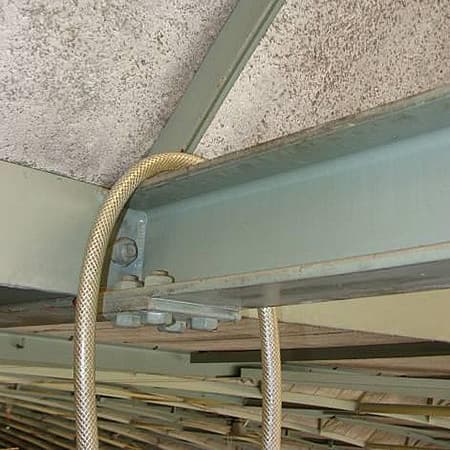
With steel positioned against the node connection
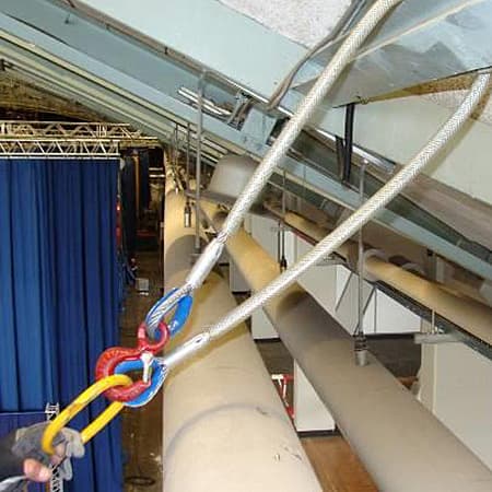
Please note:
Along the 1st and 10th purlins (above the balconies), only two-leg bridles are permitted, with an angle between 91.6° and 120°.
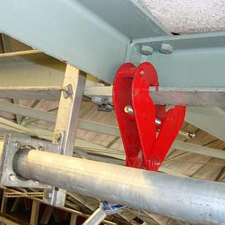
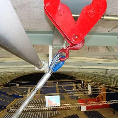
Beam clamp positioned against the node connection
Please note:
To protect the automatic blackout system: for two-leg bridles between the 5th and 6th purlins, use beam clamps on the 6th purlin.
3.2 Hall 2
In Hall 2, vertical rigging is permitted on the lower nodes of the longitudinal girders and main trusses. The use of bridles and rigging on members is not permitted. The maximum permissible load is shown in Table 3. Appendix II: Rigging Suspension Points provides an overview of the points from which rigging may be suspended.

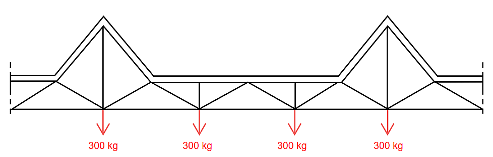
Table 3 - Maximum load and load distribution for Hall 2
| Rigging load on node | |
| Rigging to the lower nodes | |
|
Vertical direct (lower nodes) |
300 kg |
| Verticaal bridle | Not permitted |
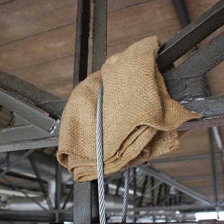
Requirements for attachment to the roof structure
3.3 Hall 3
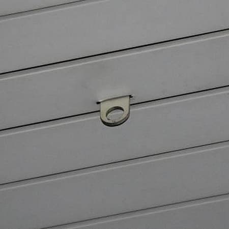
In Hall 3, vertical rigging is permitted on the lower nodes of the longitudinal girders and main trusses. The use of bridles and rigging on members is not permitted. The maximum permissible load is shown in Table 4. Appendix II: Rigging Suspension Points provides an overview of the points from which rigging may be suspended.

Table 4 - Maximum load and load distribution for Hall 3
| Rigging load on node | ||
| Rigging to the lower nodes | Rigging to the suspension eyes in the low section | |
|
Vertical direct (lower nodes) |
300 kg | 300 kg |
| Vertical bridle | Not permitted | Not permitted |
Requirements for attachment to the roof structure
3.4 Hall 4 (Amtrium)


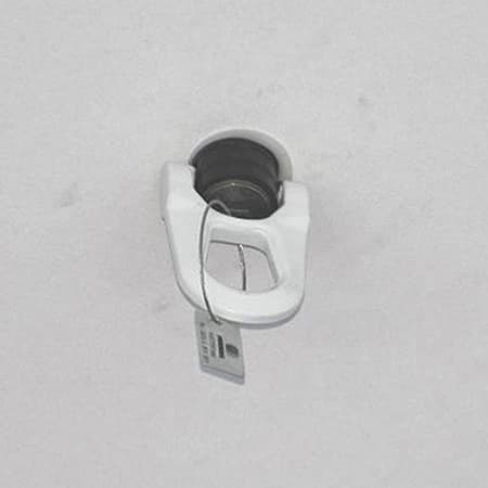
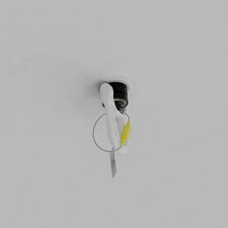
Table 5 - Maximum load and load distribution for the Amtrium
| Rigging load on suspension points | |
| Rigging to the suspension eyes in the ceiling | |
|
Vertical direct (lower nodes) |
125 kg |
| Vertical bridle | Not permitted |
Suspension Points
3.5 Hall 5
Hall 5 consists of two sections: the old section (Part A) and the new-build section (Part B). These sections have different permissible rigging loads. Appendix II: Rigging Suspension Points provides an overview of the points from which rigging may be suspended.

Part A
In Hall 5 Part A, vertical rigging is permitted on the lower nodes of the longitudinal girders and main trusses. The use of bridles and rigging on members is not permitted.
Table 6 - Maximum load and load distribution for Hall 5A
| Rigging load on node | |
| Rigging to the lower nodes | |
|
Vertical direct (lower nodes) |
300 kg |
| Vertical bridle | Not permitted |
Part B
In Hall 5 Part B, vertical rigging is permitted on all nodes (top and bottom) of the longitudinal girders and main trusses. The use of bridles and rigging on members is not permitted.
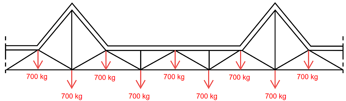
Table 7 - Maximum load and load distribution for Hall 5B
| Rigging load on nodes | |
|
Vertical direct (top and bottom chord) |
Maximum 700 kg per node |
|
Vertical bridle (top and bottom chord) |
Not permitted |
Requirements for attachment to the roof structure
3.6 Hall 6
In Hall 6, rigging is permitted from the lower and upper grids and on all nodes of the three-dimensional truss. Appendix II: Rigging Suspension Points provides an overview of the points from which rigging may be suspended. Hall 6 is notionally divided into four “rigging zones” (see Figure 13). A maximum of 8,000 kg may be suspended in each zone. The load must be distributed as follows, see talbe 8 & 9.

Table 8 - Maximum load and load distribution for members in Hall 6
| Rigging load on members 1,2,3,4,5 | ||
| Total rigging load per zone | Up to 5,000 kg | 5,000 - 8,000 kg |
| Vertical direct (top and bottom chord) |
Maximum 300 kg per member | Maximum 300 kg per member |
|
Vertical bridle (top and bottom chord) |
Maximum 300 kg per bridle subject to a maximum vertical load of 150 kg per member |
Maximum 250 kg per bridle subject to a maximum vertical load of 125 kg per member |
- A member is a part of the lower or upper chord between two nodes.
- The maximum load may be distributed over one or more suspension points per member.
- Rigging from the lighting lines beneath the members is not permitted.
- If a member in the upper chord and an adjacent member in the lower chord are used simultaneously, the maximum permissible load for these members is halved.
- If a member and a node are loaded next to each other, the member load must be added to the node load. The total weight must never exceed the maximum node load.
Table 9 - Maximum load and load distribution for nodes in Hall 6
| Rigging load on nodes 1,2,3,4 | |
| Total rigging load per zone | Up to 8,000 kg |
| Vertical direct (lower and bottom chord) |
Maximum 600 kg per node |
|
Vertical bridle (top and bottom chord) |
Maximum 1,200 kg per bridle subject to a maximum load of 600 kg per node |
- Rigging from the lighting lines beneath the nodes is not permitted
- If a node in the upper chord and an adjacent node in the lower chord are used simultaneously, the maximum permissible load for these nodes is halved.
- If a member and a node are loaded next to each other, the member load must be added to the node load. The total weight must never exceed the maximum node load.
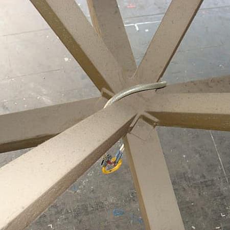
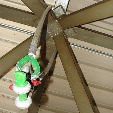
- Specific usage rules apply to rigging from the nodes; see below.
Requirements for attachment to the roof structure
3.7 Hall 7
In Hall 7, rigging is permitted on the members of the lower and upper grids and on all nodes of the three-dimensional truss. Appendix II: Rigging Suspension Points provides an overview of the points from which rigging may be suspended. Hall 7 is notionally divided into 16 “rigging zones” (see Figure 14). A maximum of 11,000 kg may be suspended in each zone.

Table 10 - Maximum load and load distribution for members in Hall 7
| Rigging load on members 1,2,3,4,5 | |
| Total rigging load per zone | Up to 11,000 kg |
|
Vertical direct (lower and bottom chord) |
Maximum 300 kg per member |
|
Vertical bridle (top and bottom chord) |
Maximum 300 kg per bridle subject to a maximum vertical load of 150 kg per member |
- A member is a part of the lower or upper chord between two nodes.
- The maximum load may be distributed over one or more suspension points per member..
- Rigging from the lighting lines beneath the members is not permitted.
- If a member in the upper chord and an adjacent member in the lower chord are used simultaneously, the maximum permissible load for these members is halved.
- If a member and a node are loaded next to each other, the member load must be added to the node load. The total weight must never exceed the maximum node load.
Table 11 - Maximum load and load distribution for nodes in Hall 7
| Rigging load on nodes 1,2,3,4 | |
| Total rigging load per zone | Up to 11,000 kg |
|
Vertical direct (top and bottom chord) |
Maximum 600 kg per node |
|
Vertical bridle (top and bottom chord) |
Maximum 1,200 kg per bridle subject to a maximum vertical load of 600 kg per node |
- Rigging from the lighting lines beneath the nodes is not permitted.
- If a node in the upper chord and an adjacent node in the lower chord are used simultaneously, the maximum permissible load for these nodes is halved.
- If a member and a node are loaded next to each other, the member load must be added to the node load. The total weight must never exceed the maximum node load.
- Specific usage rules apply to rigging from the nodes; see below.
Requirements for attachment to the roof structure
3.8 Hall 8
In Hall 8, rigging is permitted on the members of the lower and upper grids and on all nodes of the three-dimensional truss. Appendix II: Rigging Suspension Points provides an overview of the points from which rigging may be suspended. Hall 8 is notionally divided into 12 “rigging zones” (see Figure 15). A maximum of 13,000 kg may be suspended in each zone.

Table 12 - Maximum load and load distribution for members in Hall 8
| Rigging load on members 1,2,3,4,5 | |
| Total rigging load per zone | Up to 13,000 kg |
|
Vertical direct (top and bottom chord) |
Maximum 500 kg per member For the yellow-marked members on the overview plan (Appendix II: Rigging Suspension Points), a maximum of 300 kg is permitted. |
|
Vertical bridle (top and bottom chord) |
Maximum 500 kg per bridle subject to a maximum vertical load of 250 kg per member. For the yellow-marked members on the overview plan (Appendix II: Rigging Suspension Points), a maximum vertical load of 150 kg is permitted. |
- A member is a part of the lower or upper chord between two nodes.
- The maximum load may be distributed over one or more suspension points per member.
- Rigging from the lighting lines beneath the members is not permitted.
- If a member in the upper chord and an adjacent member in the lower chord are used simultaneously, the maximum permissible load for these members is halved.
- If a member and a node are loaded next to each other, the member load must be added to the node load. The total weight must never exceed the maximum node load.
Table 13 - Maximum load and load distribution for nodes in Hall 8
| Rigging load on nodes 1,2,3,4,5 | |
| Total rigging load per zone | Up to 13,000 kg |
|
Vertical direct (top and bottom chord) |
Maximum 900 kg per node |
|
Vertical bridle (top and bottom chord) |
Maximum 1,800 kg per bridle subject to a maximum vertical load of 900 kg per node |
- The maximum load may be distributed over one or more suspension points per node.
- If a node in the upper chord and an adjacent node in the lower chord are used simultaneously, the maximum permissible load for these nodes is halved.
- If a member and a node are loaded next to each other, the member load must be added to the node load. The total weight must never exceed the maximum node load.
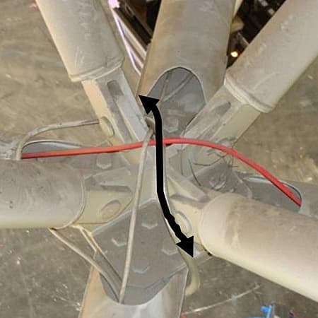
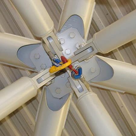
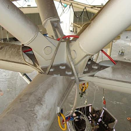
- Specific usage rules apply to rigging from the nodes; see the requirements below.
- Rigging from the eyes beneath the nodes is not permitted.
Requirements for attachment to the roof structure
3.9 Hall 9
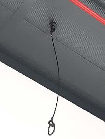
In Hall 9 (MFP), vertical rigging is possible from the suspension eyes in the ceiling. There are 204 possible suspension points in total. 180 suspension points are located at a height of 5.7 metres (hall) and 24 suspension points are located at a height of 4.4 metres (corridor). Appendix II: Rigging Suspension Points provides an overview of the points from which rigging may be suspended.
Height of suspension points
Hall height: 5.70 m
Corridor height: 4.40 m

Table 14 - Maximum load and load distribution for Hall 9
| Rigging load on the suspension point | |
| Rigging to the ceiling suspension eyes | |
|
Vertical direct (ceiling suspension eyes) |
125 kg |
| Vertical bridle | Not permitted |
Suspension points
3.10 Hall 10
In Hall 10, rigging is permitted on the members of the lower and upper grids and on all nodes of the three-dimensional truss. Appendix II: Rigging Suspension Points provides an overview of the points from which rigging may be suspended. Hall 10 is notionally divided into four “rigging zones” (see Figure 18). A maximum of 20,000 kg may be suspended in each zone.
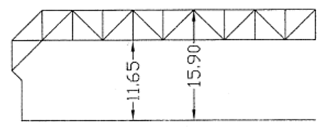

Table 15 - Maximum load and load distribution for members in Hall 10
| Rigging load on members 1,2,3,4,5 | |
| Total rigging load per zone | Up to 20,000 kg |
|
Vertical direct (top and bottom chord) |
Maximum 500 kg per member |
|
Vertical bridle (top and bottom chord) |
Maximum 500 kg per bridle subject to a maximum vertical load of 250 kg per member |
- A member is a part of the lower or upper chord between two nodes.
- The maximum load may be distributed over one or more suspension points per member.
- Rigging from the lighting lines beneath the members is not permitted.
- If a member in the upper chord and an adjacent member in the lower chord are used simultaneously, the maximum permissible load for these members is halved.
- If a member and a node are loaded next to each other, the member load must be added to the node load. The total weight must never exceed the maximum node load.
Table 16 - Maximum load and load distribution for nodes in Hall 10
| Rigging load on nodes 1,2,3,4,5 | |
| Total rigging load per zone | Up to 20,000 kg |
|
Vertical direct (top and bottom chord) |
Maximum 900 kg per node |
|
Vertical bridle (top and bottom chord) |
Maximum 1,800 kg per bridle subject to a maximum vertical load of 900 kg per node |
- The maximum load may be distributed over one or more suspension points per node.
- If a node in the upper chord and an adjacent node in the lower chord are used simultaneously, the maximum permissible load for these nodes is halved.
- If a member and a node are loaded next to each other, the member load must be added to the node load. The total weight must never exceed the maximum node load.
- Specific usage rules apply to rigging from the nodes; see the requirements below.
- Rigging from the eyes beneath the nodes is not permitted.
3.11 Hall 11
In Hall 11, rigging is permitted on the members of the lower and upper grids and on all nodes of the three-dimensional truss. Appendix II: Rigging Suspension Points provides an overview of the points from which rigging may be suspended. Hall 11 is notionally divided into four “rigging zones” (see Figure 19). A maximum of 20,000 kg may be suspended in each zone.

Table 17 - Maximum load and load distribution for members in Hall 11
| Rigging load on members 1,2,3,4,5 | |
| Total rigging load per zone | Up to 20,000 kg |
|
Vertical direct (top and bottom chord) |
Maximum 500 kg per member |
|
Vertical bridle (top and bottom chord) |
Maximum 500 kg per bridle subject to a maximum vertical load of 250 kg per member |
- A member is a part of the lower or upper chord between two nodes.
- The maximum load may be distributed over one or more suspension points per member.
- Rigging from the lighting lines beneath the members is not permitted.
- If a member in the upper chord and an adjacent member in the lower chord are used simultaneously, the maximum permissible load for these members is halved.
- If a member and a node are loaded next to each other, the member load must be added to the node load. The total weight must never exceed the maximum node load.
Table 18 - Maximum load and load distribution for nodes in Hall 11
| Rigging load on nodes 1,2,3,4,5 | |
| Total rigging load per zone | Up to 20,000 kg |
|
Vertical direct (top and bottom chord) |
Maximum 900 kg per node |
|
Verticaal bridle (top and bottom chord) |
Maximum 1,800 kg per bridle subject to a maximum vertical load of 900 kg per node |
- The maximum load may be distributed over one or more suspension points per node.
- If a node in the upper chord and an adjacent node in the lower chord are used simultaneously, the maximum permissible load for these nodes is halved.
- If a member and a node are loaded next to each other, the member load must be added to the node load. The total weight must never exceed the maximum node load.
- Specific usage rules apply to rigging from the nodes; see the requirements below.
- Rigging from the eyes beneath the nodes is not permitted.
Requirements for attachment to the roof structure
3.12 Hall 12
In Hall 12, rigging is permitted on the members of the lower and upper grids and on all nodes of the three-dimensional truss. Appendix II: Rigging Suspension Points provides an overview of the points from which rigging may be suspended. Hall 12 is notionally divided into four “rigging zones” (see Figure 20). A maximum of 14,500 kg may be suspended in each zone.
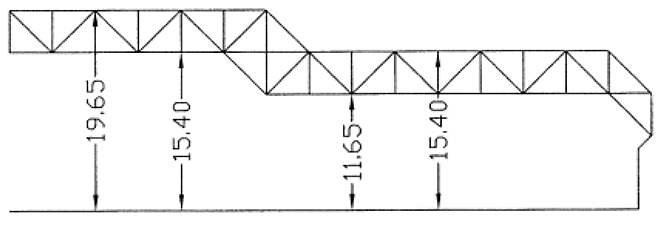

Table 19 - Maximum load and load distribution for members in Hall 12
| Rigging load on members 1,2,3,4,5 | |
| Total rigging load per zone | Up to 14,500 kg |
|
Vertical direct (top and bottom chord) |
Maximum 500 kg per member |
|
Vertical bridle (top and bottom chord) |
Maximum 500 kg per bridle subject to a maximum vertical load of 250 kg per member |
- A member is a part of the lower or upper chord between two nodes.
- The maximum load may be distributed over one or more suspension points per member.
- Rigging from the lighting lines beneath the members is not permitted.
- If a member in the upper chord and an adjacent member in the lower chord are used simultaneously, the maximum permissible load for these members is halved.
- If a member and a node are loaded next to each other, the member load must be added to the node load. The total weight must never exceed the maximum node load.
Table 20 - Maximum load and load distribution for nodes in Hall 12
| Rigging load on nodes 1,2,3,4,5 | |
| Total rigging load per zone | Up to 14,500 kg |
|
Vertical direct (top and bottom chord) |
Maximum 900 kg per node |
|
Vertical bridle (top and bottom chord) |
Maximum 1,800 kg per bridle subject to a maximum vertical load of 900 kg per node |
- The maximum load may be distributed over one or more suspension points per node.
- If a node in the upper chord and an adjacent node in the lower chord are used simultaneously, the maximum permissible load for these nodes is halved.
- If a member and a node are loaded next to each other, the member load must be added to the node load. The total weight must never exceed the maximum node load
- Specific usage rules apply to rigging from the nodes; see the requirements below.
- Rigging from the eyes beneath the nodes is not permitted.
Requirements for attachment to the roof structure
3.13 Hall 13 (Elicium)
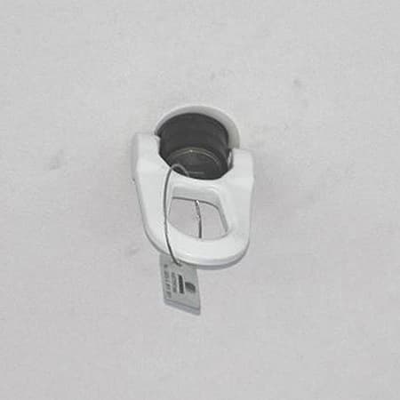
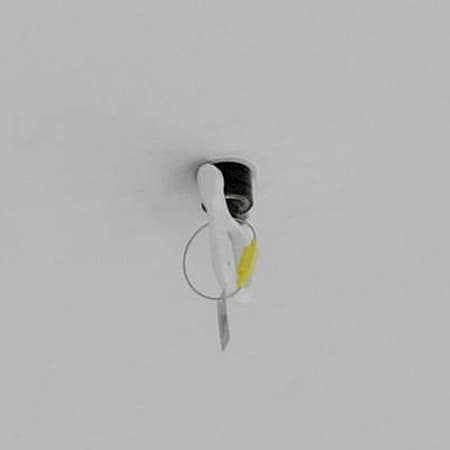
In the Elicium Ballroom, vertical rigging is possible from suspension eyes in the ceiling. There are 92 possible suspension points in total. 62 suspension points are located at a height of 6.80 metres (see the red and green dots in Figure 21) and 30 suspension points are located at a height of 8.70 metres (see the blue dots in Figure 21).
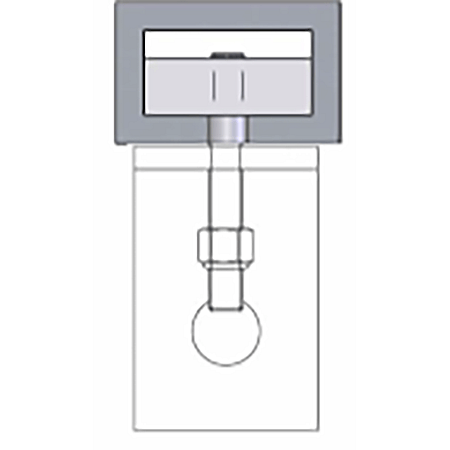
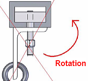
Please note: A rail runs within the roof (red line). At the indicated locations (green dots), specially developed suspension eyes can be fitted, provided no partition wall has been installed in the rail. These suspension eyes must be requested via the RAI Account Manager.

Height of suspension points
Red height: 6.80 m
Green height: 6.80 m
Blue height: 8.70 m
Table 21 - Maximum load and load distribution for Elicium Hall 13
| Rigging load on suspension points | |
| Red suspension points | Maximum 125 kg |
| Green suspension points | Maximum 125 kg |
| Blue suspension points |
If one of two adjacent nodes is loaded, the maximum load is 125 kg. If two adjacent nodes are loaded, the maximum load is 62.5 kg. |
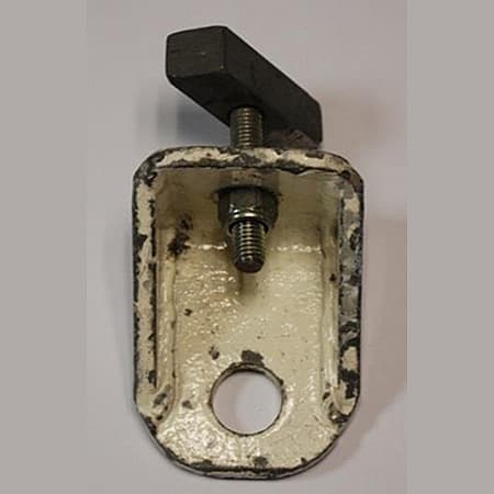
Requirements for attachment to the roof structure
Green suspension points
Red suspension points
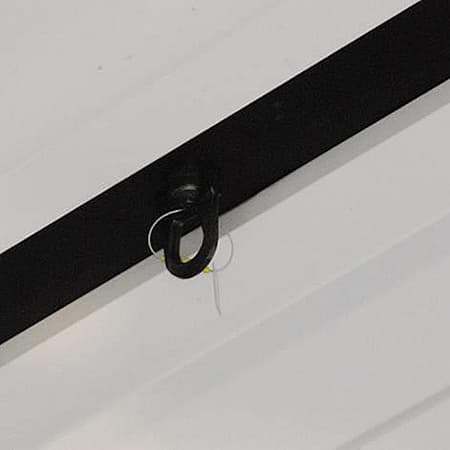
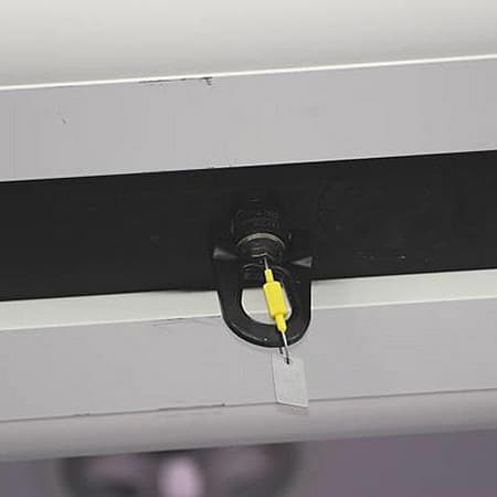
Blue suspension points
4 Entrance Areas
4.1 Entrance Area C
Entrance Area C comprises the canopy of Entrance C, Holland Terrace, Holland Lounge (Holland Mezzanine) and Rooms E103–E108.
4.1.1 Canopy C
Under the canopy, vertical rigging is permitted at the indicated locations (see Figure 23).
Please note: The canopy is fitted with bird netting, which must not be damaged.
Please note: From wind force 6 onwards, all rigging attached to the canopy must be taken down.
Height of suspension points
Height to underside: 9.50 m

Table 22 - Maximum load and load distribution for Entrance C canopy
| Rigging load on suspension eyes | |
| Suspension points | |
| Vertical direct |
250 kg per suspension point Adjacent suspension points must not be loaded to the maximum at the same time. The combined load of two adjacent suspension points must not exceed 250 kg |
| Vertical bridle | Not permitted |
4.1.2 Holland Terrace
In Holland Terrace, vertical rigging is permitted from the eyes in the ceiling.

Table 23 - Maximum load and load distribution for Holland Terrace
| Rigging load on suspension eyes | |
| Suspension points | |
| Vertical direct |
250 kg per suspension point Adjacent suspension points must not be loaded to the maximum at the same time. The combined load of two adjacent suspension points must not exceed 250 kg |
| Vertical bridle | Not permitted |
4.1.3 Holland Lounge (Holland Mezzanine)
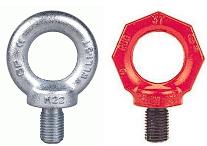
In Holland Lounge, vertical rigging is permitted from eye bolts in the ceiling. The supplier must provide certified eye bolts.

Table 24 - Maximum load and load distribution for Holland Lounge
| Rigging load on suspension eyes | |
| Suspension points | |
| Vertical direct |
150 kg per suspension point Adjacent suspension points must not be loaded to the maximum at the same time. The combined load of two adjacent suspension points must not exceed 150 kg |
| Vertical bridle | Not permitted |
4.2 Entrance Area F
Entrance Area F comprises the Park Foyer, Entrance F and the canopy of Entrance F.
4.2.1 Canopy and Reception Hall F
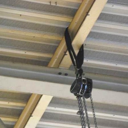
Vertical rigging is possible at the locations indicated in Figure 26. On the canopy, vertical rigging is possible on the lower chord of the 2D and 3D framework. In the reception hall, vertical rigging is permitted on the roof beams less than 50 cm from the 2D framework.
Height suspension point
Ground floor (GF)
Height: 9.50 m
First floor (FF)
Height: 7.50 m

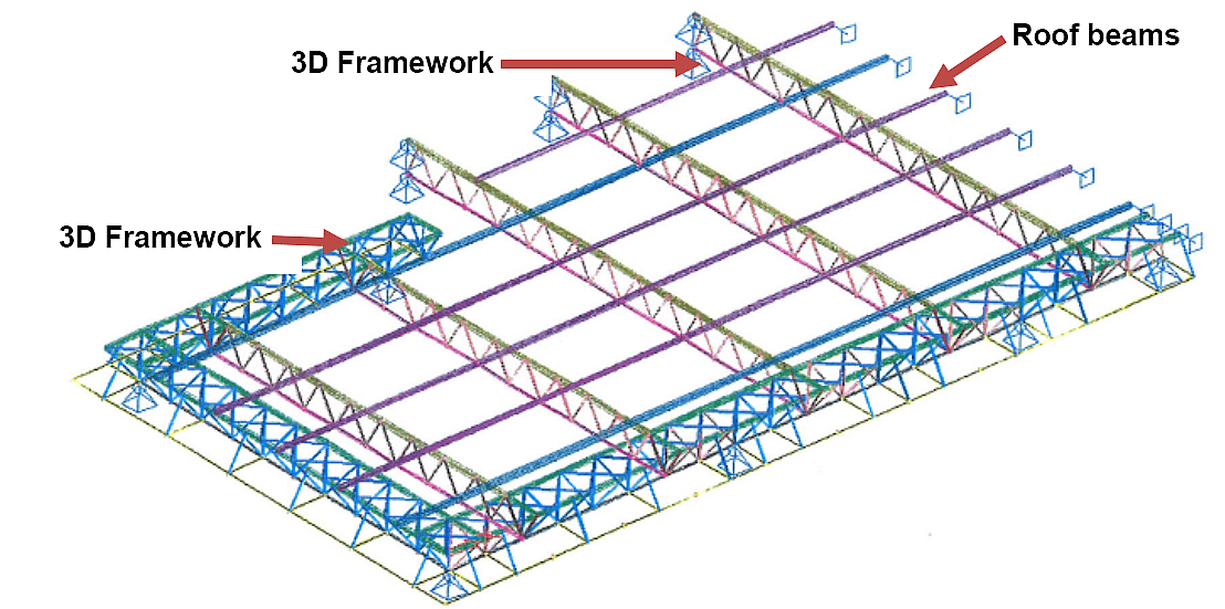
Table 25 - Maximum load and load distribution for canopy and reception hall Entrance F
| Rigging load on nodes | |
| On nodes of the lower chord of the 2D and 3D truss | |
| Vertical direct | 200 kg |
| Verticaal bridle | Not permitted |
Requirements for attachment to the roof structure
4.2.2 Park Foyer
In the Park Foyer reception hall, vertical rigging is permitted on the roof beams less than 50 cm from the 2D truss.
Height suspension point
Height: 5.60 m

Table 26 - Maximum load and load distribution for Park Foyer
| Rigging load on nodes | |
| On roof beams less than 50 cm from the 2D truss | |
| Vertical direct | 200 kg |
| Vertical bridle | Not permitted |
4.3 Entrance Area K
In Entrance Area K, vertical rigging is permitted from the suspension points in the ceiling.
Height of suspension points
Height: 7.35 m

Table 27 - Maximum load and load distribution for Entrance Area K
| Rigging load on suspension eyes | ||
| Red suspension points | Green suspension eyes | |
|
Vertical direct (top and bottom chord) |
maximum 125 kg per eye |
Rigging may be possible in consultation with Haskoning; maximum 500 kg per eye |
|
Vertical bridle (top and bottom chord) |
Not permitted | Not permitted |
5 Congress Area Rooms
5.1 Room G102 & G103
In Room G102, rigging is permitted from the suspension eyes in the ceiling.

Table 28 - Maximum load and load distribution for Room G102 & G103
| Rigging load on suspension eyes | |
|
Vertical Direct (top and bottom chord) |
Maximum 125 kg per eye |
|
Vertical bridle (top and bottom chord) |
not permitted |
Requirements for attachment to the roof structure
5.2 Auditorium Ceiling
In total, 27,500 kg may be suspended in the main hall of the auditorium. Rigging may only be suspended from the truss structures above the ceiling penetrations (see Figure 32).
Care must be taken when raising the hoists to ensure that they do not touch the ceiling (plasterboard). Make sure the chains hang vertically downwards during installation and lifting.

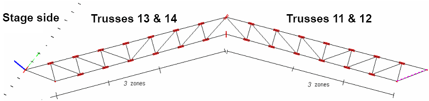
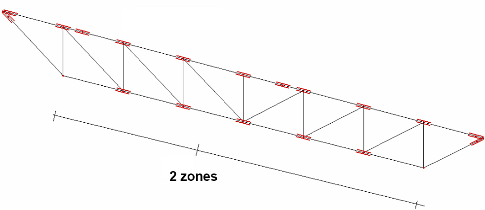
Table 29 - Maximum load and load distribution for auditorium ceiling trusses
| Truss | Vertical load per zone |
| 11 to 14 | 800 kg |
| 17 | 800 kg |
| Bridles | Not permitted |
Rafter at the level of the congress rollers
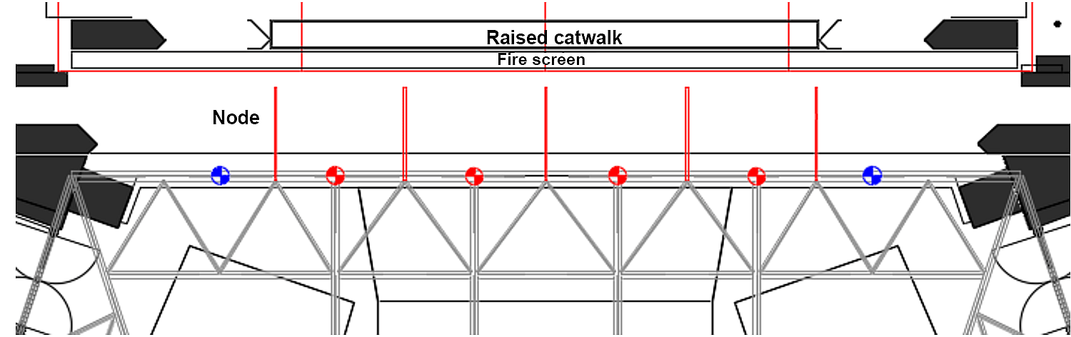

Table 30 - Maximum load and load distribution for auditorium trusses
| Rigging load on suspension point | |
| Total vertical load on truss |
1,950 kg (3,050 kg if the line array niet present) |
| Vertical load per red suspension point | 700 kg |
|
Vertical load between two red suspension points (on the top or bottom chord of the truss) |
700 kg |
| Vertical load per blue suspension point | 1,000 kg |
| Vertical load on ends of red members | 700 kg |
| Bridle | Not permitted |
5.3 Auditorium Stage Tower
In the auditorium stage tower, loads can be suspended from the fly-bar system and from the steel roof structure.
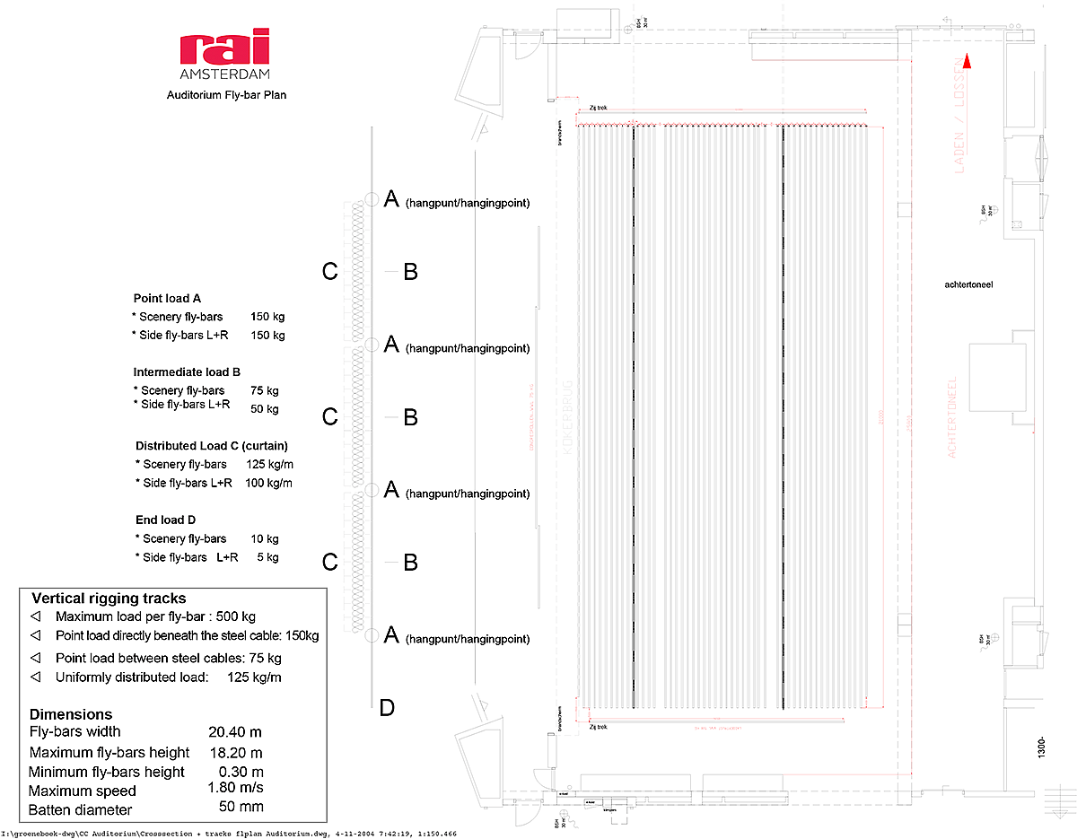
Appendix III: Auditorium Fly-Bar Plan provides an overview of the available fly bars and the permissible loads on these fly bars. The fly-bar system is controlled by a BBH computer. The installation consists of 50 fly bars and two side fly bars. The total maximum load of the fly-bar system is 25,000 kg.
The fly-bar system is suspended from the roof structure, which consists of steel trusses and beams. The permissible load on the steel structure depends on the load applied to the fly bars.


Dimensions
Height of high truss: 21.75 metres
Height of low truss: 19.85 metres
The maximum load of the tower is 34,000 kg. The load used in the fly bars must be deducted from this.
Table 31 shows, for each fly-bar load level, the additional load that may be suspended from the roof structure.
Table 31 - Maximum load and load distribution for stage tower trusses
| Fly-bar load | 0% to 50%2 | 50% to 75%2 | 75% to 100%2 |
| Maximum rigging load per truss | 9,000 kg | 4,000 kg | 4,000 kg |
| The trusses (per member)1 | |||
| Vertical | 1,500 kg | 830 kg | 830 kg |
| Bridle lower chord | 500 kg | 500 kg | 500 kg |
| Bridle upper chord | 300 kg | 300 kg | 300 kg |
| Snowfall | No restrictions | No restrictions | No rigging |
- A member is a part of the lower or upper chord between two nodes.
- Calculation of maximum roof load = 25,000 kg - (weight in fly bars) = maximum permissible load.
Tables 32 & 33 apply to the maximum permissible loads on the purlins and main beams.
Table 32 - Maximum load and load distribution for stage tower purlins
| Purlins (between two nodes) | |
| Vertical | 750 kg |
| Bridle |
250 kg (the maximum vertical component is 125 kg) |
Table 33 - Maximum load and load distribution for stage tower main beams
| Main beams (between two nodes) | |
| Vertical | 3,000 kg |
| Bridle |
600 kg (the maximum vertical component is 300 kg) |

5.4 Forum
Figure 40 shows the suspension points in the Forum. In addition to these suspension points, there are three free fly bars that may be used above the stage, of which the front fly bar is a shared fly bar.

Table 34 - Maximum load and load distribution for Forum suspension eyes
| Rigging load on suspension eye | |
|
Vertical direct (top and bottom chord) |
Maximum 150 kg per eye |
|
Vertical bridle (top and bottom chord) |
Not permitted |
Table 35 - Maximum load and load distribution for Forum fly bars
| Rigging load on fly bar | |
| Vertical per fly bar | Maximum 150 kg per fly bar |
| Point load under steel cable | Maximum 75 kg |
| Point load between steel cables | Maximum 40 kg |
Roof penetration and suspension point


Appendix I: Requirements for the Rigging Plan

I.II Example Excel calculations Rigging plot

Appendix II: Rigging Suspension Points
Appendix III: Auditorium Fly-bar Plan